
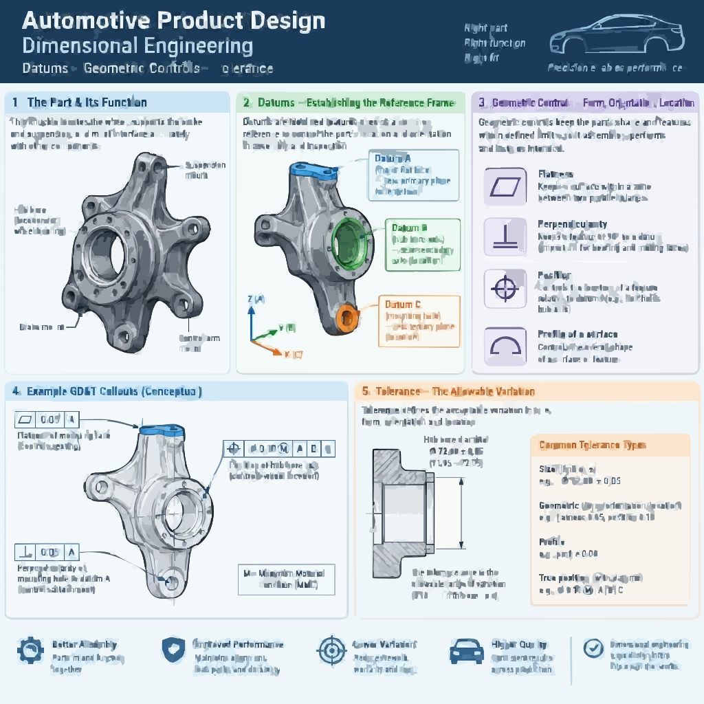
Automotive GD&T Training — Dimensional Engineering for Product Development
GD&T and dimensional engineering training: datum strategy, ASME Y14.5 controls, tolerance stack-up, inspection planning and ECR/ECN discipline. Build the analytical capability that decides whether a design actually works — across BIW, closures, interior, exterior, seating, lighting and EV enclosures.
Enquire About GD&T TrainingRequest Module Curriculum
01 · WHY THIS DISCIPLINE DECIDES
Why This Discipline Decides Whether a Design Works
Two components can each meet their own drawing and still fail to assemble. A bracket can be manufactured within every stated limit and still refuse to align with its mating part on the line. A sealing flange can pass dimensional inspection and still leak. A door can be built to specification and still show a gap that varies from vehicle to vehicle.
These are not manufacturing failures. They are dimensional engineering failures — the drawing did not define the requirement in a way that manufacturing could hold and inspection could verify, or the datum scheme did not reflect how the component is actually located.
Geometric Dimensioning and Tolerancing is the language used to close that gap. It defines the allowable variation of features in terms of function — how much position error a hole pattern can tolerate before the fastener no longer fits, how flat a sealing surface must be for the gasket to hold compression, how much profile deviation a visible surface can carry before the gap becomes unacceptable.
This discipline sits underneath every domain in automotive development. BIW, closures, interior trim, exterior systems, seating, lighting and EV enclosures all depend on it, which is why dimensional capability is tested in almost every product engineering interview regardless of the specialisation being hired for.
02 · WHAT IT CONNECTS
What Dimensional Engineering Connects
Dimensional engineering is not the act of putting symbols on a drawing. It is the discipline of holding six activities consistent with each other.
| Activities that must be kept consistent in dimensional engineering | Activities that must be kept consistent in dimensional engineering |
|---|---|
| Activity | The Question It Must Answer |
| Function | What variation can this feature tolerate before the component stops working? |
| Design definition | What datum scheme and geometric controls express that requirement unambiguously? |
| Manufacturing feasibility | Can the selected process hold this tolerance repeatedly, at rate, at acceptable cost? See DFM. |
| Assembly compatibility | Will the components locate, fasten and mate within their combined variation? See DFA. |
| Inspection | Can the requirement be measured reproducibly, using a datum scheme that matches the drawing? |
| Production quality | Is the process stable, and when it drifts, what is the root cause? See Quality Engineering. |
The failure mode this programme is built around: when any one of these six is decided in isolation, the others break. A tolerance set for function without checking process capability produces permanent nonconformance. A datum scheme chosen for modelling convenience produces inspection disputes. A stack-up that ignores assembly locating produces a component that is compliant and unbuildable.
03 · READING A DRAWING
Reading a Drawing as a Set of Requirements
Before any symbol can be applied, the drawing has to be read correctly.
Foundations covered: orthographic and sectional interpretation; linear and angular dimensioning; basic (theoretically exact) dimensions and reference dimensions; unilateral and bilateral tolerances; limit dimensioning; surface texture requirements; drawing notes and specifications; title block, revision status and drawing approval state; and the relationship between component drawings and assembly drawings.
The question learners must be able to answer: does this drawing unambiguously define what is needed to manufacture, assemble and inspect the component — and if not, where is the ambiguity and what is its consequence?
Where drawings commonly fail:
Dimensions that over-constrain a feature and conflict with each other
Tolerances applied without a stated datum
Basic dimensions given without a corresponding geometric control
Reference dimensions that a supplier treats as inspectable requirements
Revision state that does not match the released assembly
Each of these produces a specific downstream problem, and learners are trained to name it. See Documentation & Reviews.
04 · DATUM STRATEGY
Datum Strategy — the Core Skill
Datum selection is the most consequential decision in dimensional engineering, and the one most often examined in interviews, because it reveals whether a candidate understands how the part is actually used.
The principle. A datum reference frame establishes the coordinate system against which geometric tolerances are evaluated. It is built from datum features — real surfaces on the part — selected and ordered so that the frame constrains the degrees of freedom that matter for function.
Concepts covered: datum versus datum feature; primary, secondary and tertiary datum selection and ordering; degrees of freedom and constraint logic; the 3-2-1 locating concept and where it applies; datum simulators; datum targets and target areas for non-rigid parts; datum shift and applicable modifiers.
The three datum schemes that must agree
This is the insight the programme builds around, and the source of most dimensional disputes in industry:
Functional datum — the surfaces that establish the component's position in the vehicle, derived from how it mates with its neighbours.
Manufacturing datum — the locating points used in the fixture that builds or machines the part.
Inspection datum — the references used by the checking fixture or measurement machine.
When these three diverge, each function is internally consistent and the component still fails. A drawing datum that cannot be reproduced by the assembly fixture produces line-fit problems. A datum scheme that the checking fixture cannot simulate produces inspection disputes where every party is technically correct.
Non-rigid parts. Sheet-metal stampings and moulded plastic panels deform under their own weight and under fixture restraint. Their datum strategy requires targets and restraint conditions defined explicitly, and free-state versus restrained measurement must be stated. This is treated as a first-class topic, not an advanced footnote, because most automotive body and trim components fall into this category — see BIW, closures, interior and exterior.
Datum selection method taught: start from the functional interface; identify the surfaces that establish position; consider what the manufacturing fixture can actually locate on; check whether inspection can reproduce the same scheme; avoid unnecessary datum complexity; and confirm consistency between the component drawing and the assembly drawing.
05 · GEOMETRIC CONTROLS
Selecting Geometric Controls by Function
Controls are chosen because a feature has a functional requirement, not because a symbol is available.
| Control categories, characteristics and typical automotive applications | Control categories, characteristics and typical automotive applications | Control categories, characteristics and typical automotive applications |
|---|---|---|
| Control Category | Characteristics | What It Typically Protects in Automotive Components |
| Form | Straightness, flatness, circularity, cylindricity | Sealing surface integrity, locating face stability, bearing and shaft condition |
| Orientation | Parallelism, perpendicularity, angularity | Mounting face relationships, mating interface alignment |
| Location | Position | Hole patterns, pin locators, fastener interfaces |
| Profile | Profile of a line, profile of a surface | Sheet-metal and moulded surfaces, visible class surfaces, complex split lines |
| Runout | Circular runout, total runout | Rotating components, bearing and shaft interfaces |
Additional coverage: tolerance-zone shape and why it matters; composite position tolerancing and where single-segment versus composite frames apply; profile tolerancing on surfaces that carry appearance or sealing function; control of patterns as a group rather than feature by feature; the relationship between size and geometric tolerance; and the two errors that dominate practice — over-tolerancing, which adds cost with no functional benefit, and under-tolerancing, which produces nonconformance and assembly failure.
The discipline the programme enforces: for every control specified, the learner must state the functional requirement it protects, the datum frame it references, and the inspection method that will verify it. A control that cannot survive those three questions is removed or replaced.
06 · MATERIAL CONDITION
Material Condition Modifiers and Functional Gauging
Material condition modifiers are where dimensional theory meets assembly reality, and where many candidates lose interview marks.
Concepts covered: Maximum Material Condition (MMC); Least Material Condition (LMC); Regardless of Feature Size (RFS) where applicable; bonus tolerance and how it is calculated; virtual condition and resultant condition boundaries; datum feature material boundary modifiers; and fixed versus floating fastener conditions.
Why bonus tolerance exists. A hole at its maximum material size has the least clearance available, so its position tolerance must be tightest. As the hole departs from maximum material and becomes larger, more clearance exists, and additional position tolerance can be permitted without compromising assembly. That additional allowance is the bonus, and it converts directly into manufacturing tolerance and cost.
Virtual condition and gauge design. The virtual condition boundary defines the worst-case envelope a feature can occupy. From it, a functional gauge can be designed — a hard gauge that accepts the part if it assembles. This connects drawing requirements directly to a physical verification device, and learners build the gauge concept as part of the calculation.
Where LMC applies. Not every feature should use MMC. LMC is used where a minimum wall thickness, edge distance or structural section must be protected — the concern is not assembly clearance but material integrity. The programme teaches the selection logic rather than a default.
The calculation the learner must perform independently: given a hole pattern, its size limits, its position tolerance and the datum references, calculate the virtual condition, calculate available bonus at a stated actual size, and determine whether the mating fastener will assemble. See Tolerance Stack-Up.
07 · LIMITS & FITS
Limits, Fits and Interface Relationships
Coverage: clearance, interference and transition fits; hole-basis and shaft-basis systems; upper and lower size limits; allowance and clearance calculation; press-fit and locating-fit considerations; bearing and shaft interface requirements; fastener and mounting-hole relationships; and application of ISO limits and fits where the drawing specifies them.
Engineering application: determining the correct dimensional relationship for mounting, locating and functional interfaces — and recognising that a fit decision is a functional decision with manufacturing and cost consequences, not a table lookup.
08 · TOLERANCE STACK-UP
Tolerance Stack-Up and Variation Analysis
Stack-up is the calculation that predicts whether an assembly will work before anything is built. It is the single most interview-tested analytical skill in this discipline. See Tolerance Stack-Up for the dedicated method subject.
Identify the functional requirement — the gap, clearance, flush, compression or alignment that must be met.
Establish the dimensional chain — every dimension and tolerance that contributes to that requirement.
Determine direction and sign of each contribution.
Identify fixed and floating interface conditions.
Compute the worst-case result — the arithmetic extreme, which assumes every contribution at its limit simultaneously.
Compute the statistical (RSS) result — the root-sum-square estimate, which assumes contributions vary independently and randomly.
Compare both against the requirement and judge which method is appropriate for the consequence of failure.
Identify the dominant contributors and allocate tolerance where it buys the most functional benefit per unit of cost.
Why both methods matter. Worst-case is conservative and appropriate where failure is safety-relevant or assembly-stopping. Statistical analysis reflects real production behaviour and is appropriate where contributions vary independently — but it carries a defined risk of exceeding the limit, and that risk has to be accepted deliberately rather than assumed away. An engineer who applies RSS everywhere, or worst-case everywhere, has not understood the choice.
Applications covered: assembly clearance and interference prediction; gap and flush variation between adjacent components (see Exterior, Closures); sealing and gasket compression stack-up (see EV enclosure); multi-part welded assemblies (see BIW); and 2D chain concepts where direction matters.
Beyond 1D: introduction to 2D vector chains and awareness of 3D variation analysis, sensitivity analysis, tolerance allocation, and correlation between predicted and measured variation. These are covered as awareness so that learners can work with specialists rather than replace them.
09 · INSPECTION
Inspection and Measurement Engineering
A requirement that cannot be verified is not a requirement. This section closes the loop between drawing and production. See Quality Engineering.
Coverage: metrology fundamentals and measurement principles; hand-instrument application and its limits; Coordinate Measuring Machine fundamentals and datum alignment; checking fixtures and functional gauges; Gauge Repeatability and Reproducibility (GR&R); measurement uncertainty; calibration and traceability; inspection planning; First Article Inspection; dimensional reporting; and nonconformance identification.
The correlation problem. Design intent, inspection method and assembly condition must align. A CMM alignment that uses a different datum sequence than the drawing specifies will produce results that are precise and wrong. A checking fixture that simulates the assembly condition may disagree with a CMM measurement of the same part in free state — and both may be correct for their stated purpose. Learners are trained to ask which condition the requirement is defined against before treating a measurement as evidence.
Measurement system performance. GR&R determines whether the measurement system can distinguish good parts from bad. Where gauge variation consumes a large share of the tolerance, the inspection decision becomes unreliable regardless of how carefully the operator works. This is taught as a design consequence: a tolerance the measurement system cannot resolve is a tolerance that will generate disputes.
10 · DOMAIN APPLICATIONS
Domain Applications
The same control carries different engineering purpose depending on the component. Learners apply the discipline across the domains where it decides quality.
| Domains and where dimensional engineering decides the outcome | Domains and where dimensional engineering decides the outcome |
|---|---|
| Domain | Where Dimensional Engineering Decides the Outcome |
| Body-in-White | Mounting-hole position and datum strategy; welding fixture and locating-point design; sheet-metal profile and flange control; body aperture and structural interface variation |
| Closures | Hinge and striker positioning; hood and tailgate mounting interfaces; door aperture control; gap and flush variation; functional adjustment range |
| Interior trim | Instrument panel mounting interfaces; plastic trim locating features; clip and fastener positions; console and door trim fitment; interfaces that drive squeak and rattle |
| Exterior | Bumper mounting and attachment points; fender and body interface; exterior plastic profile; lamp and grille alignment; surface consistency |
| Lighting | Headlamp mounting references; lamp-to-body alignment; lens and housing interfaces; adjustment mechanism positioning; sealing requirements |
| Seating | Seat mounting and anchorage interfaces; rail and mechanism alignment; bracket hole positioning; frame dimensional relationships |
| EV battery enclosure | Enclosure mounting interfaces; sealing flange flatness and profile; bolt-hole pattern position; gasket compression variation under thermal movement |
| Powertrain and rotating assemblies | Shaft and bearing interfaces; runout and cylindricity requirements; bearing fits and clearances; rotational dimensional requirements |
Detailed domain construction is covered on the respective domain pages; here the focus is on how dimensional requirements are established, argued and verified within each.
11 · METHODS INTEGRATION
Methods Integration — DFM, DFA, DFMEA and Validation
Dimensional engineering does not stand alone. It is the connective tissue between the methods, and the programme treats it that way.
DFM — Design for Manufacturing. A tolerance must be achievable by the selected process. Stamping and forming variation, injection-moulding shrinkage and warpage, casting capability, machining capability and welding distortion all define what the drawing can realistically demand. Datum accessibility in the fixture is part of this assessment. The expected skill: identify whether a specified tolerance can be held consistently, and recommend a technically justified alternative without compromising function.
DFA — Design for Assembly. Dimensional requirements exist to make assembly work. Locating arrangements, fastener and hole alignment, assembly clearance, interference conditions, clip and locator interfaces, assembly sequence and access all determine whether the dimensional scheme supports repeatable build. The expected skill: ensure the dimensional requirements produce correct, repeatable assembly rather than requiring adjustment on the line.
DFMEA — dimensional risk. Dimensional failure modes are specific: incorrect position, misalignment, interference, excessive clearance, sealing failure, and assembly-stopping nonconformance. Linking each to the geometric control that prevents it, and to the validation activity that confirms it, is what converts a DFMEA from paperwork into risk control.
DVP&R — dimensional validation. Critical dimensional requirements map to verification methods, acceptance criteria and result records. Prototype and first-article results are compared against the drawing, deviations investigated, corrective actions verified, and traceability maintained between requirement and evidence.
APQP, PPAP, MSA, SPC. Learners understand how a dimensional requirement travels from drawing into control plan, measurement system analysis, process capability monitoring and production approval — and why a requirement that bypasses any of those stages becomes a launch issue.
12 · CHANGE CONTROL
Change Control on a Dimensional Requirement
A dimensional change looks small and travels far. A revised hole position can move the fixture, the checking gauge, the supplier's inspection plan, the mating component's clearance, the validation status and the drawing revision — simultaneously. See ECR/ECN.
ECR — Engineering Change Request. Identify the failure or improvement; analyse the assembly and manufacturing problem; evaluate the functional requirement; assess the effect on datums, tolerances and the stack-up; document the technical justification; and submit for cross-functional review.
DCR — Design Change Request. Where the organisation uses this terminology, a design change is initiated or documented within the change-control process. The definition and its relationship to the ECR depend on the organisation's procedure, so the control principle is taught rather than one company's form.
ECN — Engineering Change Notice. Communicate the approved change: drawing revision updates, implementation timing, tooling and fixture impact, inspection plan updates, supplier and manufacturing communication, and documentation traceability.
A worked scenario the programme uses. A bracket repeatedly fails to align with its mating assembly during production. The learner must establish the actual failure condition; check the drawing's datum scheme and position tolerance; compare the inspection and assembly locating methods; investigate manufacturing variation; evaluate the effect of a proposed change; review DFM and DFA implications; assess tooling, checking fixture and inspection impact; route the change through the applicable process; and verify that the change actually resolved the problem rather than moving it.
13 · STANDARDS FRAMEWORK
Standards Framework — with Applicability Discipline
Learners are taught to identify the governing standard, the customer requirement and the drawing-specific rules before interpreting or applying anything.
| Standards references and their relevance | Standards references and their relevance |
|---|---|
| Reference | Relevance |
| ASME Y14.5 | Geometric dimensioning and tolerancing — the edition cited on the customer drawing governs |
| ASME Y14.5.1 | Mathematical definition of dimensioning and tolerancing principles |
| ISO 1101 | Geometrical tolerancing |
| ISO 5459 | Datums and datum systems |
| ISO 8015 | Fundamental GPS concepts and principles |
| ISO 286 | Limits and fits |
| ISO 14253 series | Inspection by measurement and conformity decision |
| IATF 16949 | Automotive quality management system requirements — see Quality Engineering |
| AIAG APQP, PPAP, MSA, SPC | Core automotive quality methods — see APQP & PPAP |
Applicability discipline — stated explicitly and enforced in the programme. ASME and ISO GPS are separate interpretation frameworks with different default rules, and they are not to be mixed on one drawing. The applicable edition, revision and framework are determined by the customer drawing and programme requirements, not by preference. Standards are revised, and the current status must be verified for each programme. The programme teaches interpretation and application. It does not confer certification, and it does not substitute for the customer specification governing a specific drawing.
14 · PROJECT WORK
Project Work and Portfolio Evidence
Projects are calculation and documentation exercises with a written position at the end. They are representative learning studies, not confidential OEM programmes.
| Projects, decisions defended and portfolio evidence | Projects, decisions defended and portfolio evidence | Projects, decisions defended and portfolio evidence |
|---|---|---|
| Project | Decisions the Learner Defends | Portfolio Evidence |
| Drawing interpretation and dimensional review | Which dimensions are functional; which feature control frames are clear and which are ambiguous; whether the specified tolerances can be manufactured and inspected as drawn | Interpretation report with identified ambiguities and recommended corrections |
| Datum strategy for a body bracket | Functional versus manufacturing versus inspection datum selection; 3-2-1 constraint logic; non-rigid behaviour and datum targets; stamping and welding fixture considerations | Datum strategy justification, annotated drawing, inspection approach |
| MMC, bonus tolerance and virtual condition | Material condition selection logic; bonus calculation; virtual condition boundary; functional gauge concept; acceptance conditions | Calculation sheet, virtual condition derivation, gauge concept |
| Multi-component tolerance stack-up | Chain identification; worst-case and RSS computation; dominant contributors; tolerance allocation against cost and capability; choice of method against consequence of failure | Worked stack-up sheet, contributor analysis, allocation recommendation |
| Interior interface fitment study | Datum relationships across plastic and body structure; hole-position requirements; gap variation chain; recommended control improvements | Interface dimensional review with stack-up evidence |
| EV enclosure sealing interface | Gasket compression requirement as a dimensional chain; sealing surface flatness and profile; bolt-hole position; flange stiffness and thermal movement contribution | Sealing interface analysis, stack-up sheet, critical characteristic list |
| Inspection and gauge planning | Measurement method selection against requirement; datum simulation; checking fixture concept; CMM alignment; GR&R and uncertainty considerations | Dimensional inspection plan with gauge concept |
| Dimensional change evaluation | Root cause rather than symptom; drawing assessment; DFM/DFA implications; tooling and inspection impact; controlled release | Change evaluation report with ECR-to-ECN documentation |
Assessment weighs technical correctness, calculation accuracy, functional justification, manufacturing and assembly feasibility, inspection feasibility, documentation discipline and defensibility under questioning. Work that cannot survive review questioning is reworked rather than passed.
15 · COURSE OUTCOMES
Course Outcomes
What a learner can demonstrate at the end of this discipline, across interpretation, datum strategy, controls, calculation, inspection and change.
| Outcome areas and learner capability | Outcome areas and learner capability |
|---|---|
| Outcome Area | Learner Can Demonstrate |
| Drawing interpretation | Read a drawing as a set of functional requirements and identify ambiguity, conflict and over-constraint |
| Standards application | Apply the governing framework and edition correctly, and recognise why ASME and ISO GPS are not interchangeable |
| Datum strategy | Establish a functional datum reference frame and verify that it can be reproduced by manufacturing fixtures and inspection |
| Non-rigid components | Define datum targets and restraint conditions for sheet-metal and moulded parts, and distinguish free-state from restrained measurement |
| Control selection | Select form, orientation, location, profile and runout controls against a stated functional requirement, and reject controls that cannot be justified |
| Material condition modifiers | Apply MMC and LMC correctly, calculate bonus tolerance and virtual condition, and design a functional gauge concept |
| Limits and fits | Determine appropriate dimensional relationships for mounting, locating and functional interfaces |
| Tolerance stack-up | Perform 1D and 2D worst-case and RSS analysis, identify dominant contributors, and justify the method chosen |
| Inspection engineering | Specify measurement methods, datum simulation, checking fixture and CMM alignment, and evaluate measurement system performance |
| Methods integration | Judge whether a tolerance is manufacturable (DFM), whether the dimensional scheme supports repeatable assembly (DFA), and link dimensional risks to validation (DFMEA, DVP&R) |
| Change control | Evaluate a dimensional change across tooling, inspection, interfaces and validation, and control release with traceability (ECR/ECN) |
| Technical communication | Explain a datum choice, a control choice and a stack-up result, and defend them under questioning |
These outcomes represent learning capability. Completion does not confer independent design-release authority, OEM approval competence or professional certification. Those require programme-specific responsibility, demonstrated performance and, where applicable, formal certification.
16 · CAREER OUTCOMES
Job Opportunities
Roles this discipline supports, and what the work typically involves.
| GD&T and dimensional roles and typical work | GD&T and dimensional roles and typical work |
|---|---|
| Role | What the Work Involves |
| GD&T Engineer | Drawing interpretation, geometric control application, datum selection and dimensional review |
| Dimensional Engineer | Component dimensional control, assembly variation analysis and measurement coordination |
| Tolerance Stack-up Analyst | Dimensional chain calculation, clearance and interference analysis, variation prediction |
| Quality / Dimensional Quality Engineer | Inspection planning, measurement analysis, nonconformance investigation and quality reporting (Quality Engineering) |
| Manufacturing Engineer (dimensional focus) | Process capability, fixture considerations, feasibility and dimensional problem-solving (DFM) |
| Automotive Product Design Engineer | Functional dimensioning, interface definition, tolerance allocation and design validation |
| Supplier Quality Engineer | Supplier dimensional requirements, inspection documentation, production approval evidence and corrective action (APQP/PPAP) |
| Metrology / Inspection Engineer | Measurement method selection, CMM fundamentals, checking fixtures, calibration and measurement-system evaluation |
Employer types: passenger vehicle OEMs, Tier-1 and Tier-2 suppliers, engineering and R&D service providers, body and sheet-metal manufacturers, plastic moulding suppliers, lighting and seating suppliers, EV component and battery enclosure manufacturers, and precision machining organisations.
Job titles and responsibilities vary by company. Some positions also require software operation proficiency, CAE capability, PLM experience or formal certification; candidates should verify requirements in the specific job description.
18 · WHO SHOULD TAKE THIS DISCIPLINE
Who Should Take This Discipline
This discipline supports every domain, so it suits learners building dimensional capability as their primary specialisation or as a supporting skill alongside a domain module.
Mechanical and automobile engineering students who want dimensional capability before placements, because it appears in interviews across every domain — start with Automotive Fundamentals.
Fresh graduates entering design, manufacturing or quality roles who will be handed drawings in their first week.
Production and quality engineers who investigate nonconformance and need to determine whether the cause is process, measurement or specification.
Design engineers in BIW, interior, exterior, seating or EV who allocate tolerances and need the analytical basis for the allocation.
Supplier quality and metrology personnel who review inspection documentation and resolve disputes.
Career-restart engineers refreshing a skill that is used continuously in every product development role.
Assumed foundation: engineering drawing interpretation, basic mechanical engineering and dimensional awareness. No prior GD&T study is required for the foundation pathway; the programme builds from drawing interpretation upward.
19 · FREQUENTLY ASKED QUESTIONS
Frequently Asked Questions
1. What is actually wrong with plain plus-minus tolerancing?
2. Why do interviewers spend so much time on datum selection?
3. How much mathematics is involved, and will I be able to handle it?
4. Is ASME certification necessary to get a dimensional engineering role?
5. Why does a stack-up done on paper matter when we can just build a prototype?
6. How do I decide between worst-case and RSS analysis?
7. Are ASME Y14.5 and ISO GPS interchangeable?
8. Why does the same part measure differently in free state and in a checking fixture?
9. Which deliverables should a fresher include in a dimensional engineering portfolio?
10. How do interviewers test GD&T in technical rounds?
CONTINUE LEARNING
Explore Related Domains & Methods
Dimensional engineering underpins every automotive domain and connects to every product-development method. Continue into the related pages below.
BIW EngineeringClosures EngineeringInterior Product EngineeringExterior Product EngineeringSeating EngineeringEV EngineeringLighting EngineeringComponent EngineeringMaterials EngineeringManufacturing ProcessesJoining TechnologyPackaging & InterfacesTolerance Stack-UpDFMDFADFMEADVP&RAPQP & PPAPECR & ECNQuality EngineeringDocumentation & ReviewsCase StudiesPractical AssignmentsInterview Preparation
Build your automotive engineering knowledge
Explore the technical subjects or contact MYTECHLEARN about your learning objectives.
Enquire Now