
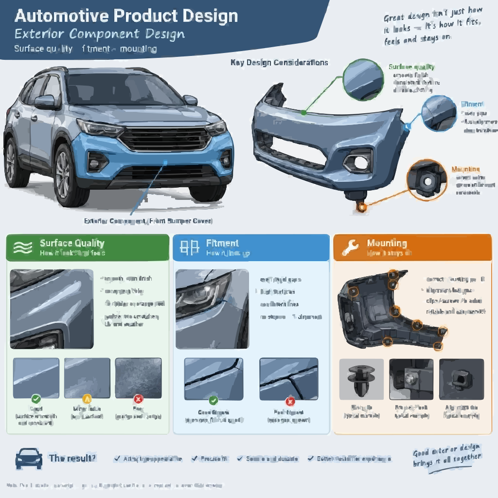
Automotive Exterior Design Training — Systems, Surfaces and Sensor Integration
Exterior engineering training across bumper systems, fascias, grilles, ADAS sensor packaging, large-part plastic DFM, gap and flush, and ECR/ECN control. Build production-ready exterior competence for OEM and Tier-1 roles — with emphasis on engineering decisions and production readiness.
Enquire About Exterior TrainingRequest Domain Curriculum
01 · WHAT EXTERIOR DECIDES
What Exterior Engineering Actually Decides
An exterior component is judged on three separate fronts at once, and the difficulty is that the three pull against each other. It must look correct — surface continuity, gap and flush against painted metal, colour and gloss consistency across a long span. It must survive — sunlight, monsoon, temperature swing, stone strike, high-pressure wash, kerb contact. And it must function — manage impact energy, feed cooling air, and let radar and cameras see through it without distortion.
Exterior engineering is the discipline of holding all three in one component. A fascia that looks perfect but warps in service fails. A fascia that survives but cannot be released from the tool at rate fails. A fascia with a beautifully integrated sensor that the radar cannot see through fails most expensively of all.
This domain trains the decisions that hold those requirements together: system architecture, large-part moulding feasibility, attachment strategy across long spans, dimensional control at visible joints, sensor-transparent packaging and controlled engineering change. Learners are assessed on whether their decisions survive review questioning — not on how a surface renders.
02 · COMPONENT ARCHITECTURE
Component Architecture and Interface Map
Exterior parts are studied as a system network. No exterior component is developed alone, because every visible joint and every mounting point is shared with a neighbouring system.
| Exterior component groups, engineering roles and interfaces | Exterior component groups, engineering roles and interfaces | Exterior component groups, engineering roles and interfaces |
|---|---|---|
| Component Group | Engineering Role | Interfaces That Constrain It |
| Front bumper assembly | Fascia, energy absorber, reinforcement beam, crash boxes, brackets, grilles, sensor provisions, tow-eye cover, lower closeouts | BIW front structure, fenders, headlamps, radiator support, pedestrian-protection envelope, radar and camera |
| Rear bumper assembly | Rear fascia, absorber and reinforcement interfaces, valance, diffuser, reflectors, sensor and camera provisions | BIW rear structure, quarter panels, tail lamps, tailgate, exhaust and thermal clearance, tow provisions |
| Fenders and wheel arches | Outer surface, wheel and tyre clearance envelope, liner attachment, stone-chip protection | Hood, doors, bumper fascias, headlamps, suspension travel envelope, liners |
| Rocker cladding and side mouldings | Lower-body protection, side appearance, door-opening clearance | Rocker panel, door edges, wheel-arch trims, jacking and lifting provisions |
| Grille and air intakes | Cooling airflow, front-end identity, sensor and active-shutter integration | Fascia, radiator and condenser, EV thermal module, radar, pedestrian-protection geometry |
| Spoilers, roof rails and appliqués | Aerodynamic function, appearance, attachment durability | Roof or decklid structure, rear glass, attachment boss locations, vibration environment |
| Underbody shields and deflectors | Aerodynamic closeout, contamination protection, battery protection in EVs | BIW floor, powertrain or drive unit, battery enclosure, thermal components |
Working insight the programme insists on: a visible exterior joint is produced by components from different suppliers, often in different materials, attached to a body structure built to its own tolerance. Making that joint look correct is a dimensional-engineering problem long before it is an appearance problem.
03 · STYLING TO ENGINEERING
Styling-to-Engineering Translation
Styling defines the surface; engineering decides whether the surface can exist as a part.
Class-A surface requirements. The visible surface carries continuity, reflection and highlight requirements. Engineering must preserve those while placing every attachment, rib and gate location on the hidden side.
Part splits and boundaries. Where the component is divided determines tooling size, moulding feasibility, joint lines, service removal and the number of suppliers involved. Split strategy is an engineering decision made early and expensive to change later.
A-side and B-side discipline. The A-side is what the customer sees and what quality is judged on. The B-side carries ribs, bosses, brackets, locating features, clip towers and reinforcements. The engineering obligation is absolute: B-side features must not produce sink, read-through or distortion on the A-side. Almost every large-part DFM failure in exterior components traces back to a B-side feature that was added for structure without checking its appearance consequence.
Packaging reality. Available depth between the styled surface and the structure behind it determines what reinforcement, absorber and sensor packaging is possible. A styling change of a few millimetres can eliminate the crush space a bumper system was relying on. See Packaging & Interfaces.
04 · BUMPER SYSTEMS
Bumper Systems as Engineered Systems
The bumper is the clearest example of a component that must be understood as a system, not a part. Each element carries a different function, and a change to one propagates through the rest.
| Bumper system elements, functions and engineering constraints | Bumper system elements, functions and engineering constraints | Bumper system elements, functions and engineering constraints |
|---|---|---|
| Element | Function | Engineering Constraint |
| Fascia (cover) | Visible appearance, grille and lamp openings, sensor provisions, environmental protection of underlying parts | Large-part moulding feasibility, thermal expansion across span, paint or moulded-in-colour finish, pedestrian-protection geometry |
| Energy absorber | Manages low-speed impact energy through controlled deformation | Must be packaged within the available depth; material and geometry set the energy absorption behaviour |
| Reinforcement beam | Distributes impact loads and transfers them into the structure | Section and material determine load distribution; must not compromise the pedestrian-protection envelope |
| Crash boxes and mountings | Controlled deformation and connection to the body structure | Dictate the load path into the BIW and the repair strategy after impact |
| Brackets, side retainers and clips | Position the fascia, control fitment, allow service removal | Stiffness and clip strategy determine whether the fascia stays located and gaps stay stable |
Low-speed damageability and repairability. A bumper system is designed against defined low-speed impact conditions, and the engineering outcome that matters commercially is what gets damaged and what it costs to repair. Damage transfer into the body structure, or into a reinforcement that cannot be replaced independently, converts a minor incident into a major repair. Learners evaluate this as a design outcome, not an afterthought.
Rear bumper specifics. The rear system adds tail-lamp and quarter-panel interfaces, tailgate clearance, exhaust thermal management and service access, and the rear-impact load path differs from the front. These are treated as distinct engineering constraints rather than a mirrored front-bumper exercise.
Boundary. Impact performance values, test conditions and acceptance criteria come from the applicable vehicle programme and regulation. The programme teaches system architecture, load-path reasoning and the design implications of validation feedback; it does not deliver crash simulation or certification capability.
05 · PEDESTRIAN PROTECTION
Pedestrian Protection — Packaging Awareness
Front-end geometry is constrained by pedestrian-protection requirements, and the constraint reaches the fascia, the grille, the bonnet leading edge and the structure beneath them.
What exterior engineers must understand: the lower-leg impact zone and the deformation space available behind the fascia; the role of the absorber and any compliant front-end structure; the leg-impact implications of grille and lamp geometry; and the fact that a reinforcement placed for low-speed damageability can compromise the deformation space needed for pedestrian protection.
Boundary. This is packaging awareness and coordination, not certification. Regulatory interpretation, impact-modelling and homologation sit with the authorised safety engineering process and the applicable regulation for each market. A generic design rule cannot substitute for that validation, and the programme states so explicitly.
06 · AIRFLOW & THERMAL
Grille, Airflow and Thermal Management
The front-end opening is an airflow device that also has to look right.
Engineering subjects: grille open area against cooling demand; duct and intake routing to the radiator, condenser or EV thermal module; interaction with the reinforcement beam and absorber packaging; drainage and contamination management; and the appearance requirements that constrain open area and mesh geometry.
Active grille shutters. Where fitted, the shutter assembly adds actuator and linkage packaging, vane clearance, sealing in the closed position, retention, drainage and exposure to ice and contamination. It also changes the fascia's structural and service context, since the shutter becomes a serviceable mechanism behind a visible surface.
EV front-end reality. Without a radiator demand of the same magnitude, the front-end opening often reduces or closes, and aerodynamic efficiency becomes the dominant driver of front-end shape. That shift changes grille design, underbody shielding, wheel-arch air management and the thermal-management interfaces behind the fascia — and it is why exterior engineers working on EVs reason about drag and cooling together.
07 · ADAS SENSOR INTEGRATION
ADAS Sensor Integration — the Exterior Engineer's Constraint
This is where exterior engineering has changed most in the last decade, and where candidates are most often exposed in interviews.
Radar behind the fascia. A radar module mounted behind a bumper cover requires a defined window through the fascia. That window has to satisfy several constraints simultaneously: material compatible with RF transmission; uniform wall thickness across the window; no metallic paint or metallic-effect coating in the transmission path; no ribs, bosses or structural features crossing the window; and no air gaps or intermediate layers that refract the signal. A visually acceptable fascia with a structural rib behind the radar face can produce a sensor that reports false targets or loses detection — a safety-relevant failure originating in an appearance component.
The governing thickness, material and paint specification must come from the sensor supplier and the OEM specification. The programme teaches the constraint and the coordination route rather than quoting a universal value.
Camera systems. Clear field of view, mounting accuracy and rigidity, protection from water and contamination, cleaning and service access, and vibration and thermal stability all constrain the bracket and the surrounding fascia geometry.
Ultrasonic parking sensors. Correct mounting orientation, seating and opening geometry, coating compatibility, retention, sealing, and alignment of the sensor to the fascia surface. A sensor that sits proud or recessed relative to the styled surface produces detection errors and an appearance defect at the same time.
Cross-functional reality. The exterior engineer owns the geometry that determines whether the sensor works, while the sensor and software teams own the function. The programme trains engineers to hold that interface — specifying, documenting and defending the packaging requirement — rather than treating sensors as someone else's problem.
08 · LARGE-PART DFM
Large-Part Plastic DFM
Exterior mouldings are large, appearance-critical and expensive to tool. DFM failures here are measured in tooling rework and launch delay.
Warpage and thermal shrinkage. Long parts are prone to warpage because shrinkage is never perfectly uniform and cooling is never perfectly balanced. The engineering responses are balanced wall sections, considered gate location, packing strategy, balanced cooling, and attachment strategy that accommodates residual movement rather than fighting it. Filled polymer grades are frequently selected for dimensional stability across long spans — but the grade choice must be made against impact, appearance and process requirements, not on stability alone.
Sink and read-through. Thick sections, heavy ribs and boss pads cool more slowly and pull the visible surface in. On a large painted or moulded-in-colour surface, even slight read-through is a quality rejection. Rib thickness relative to nominal wall, boss stand-off and gusset design are the controlling decisions.
Gate and weld-line placement. Gate position determines flow, packing and where weld lines form. On an exterior face, a gate mark or weld line in a visible area is a defect regardless of whether the part is structurally sound. Gate location is therefore an appearance decision as much as a process one.
Parting lines and tooling splits. Parting-line placement must satisfy appearance (hide the line from the occupant and pedestrian viewing angle), tooling (permit release and avoid fragile shut-offs) and function (seal, drainage, attachment). Large parts often require multiple tooling splits, and each split introduces a potential flash or mismatch location.
Undercuts and side actions. Side actions add tooling cost and maintenance. Each undercut must be justified against the functional or appearance requirement it serves, or eliminated.
Draft. Draft must suit the material, texture and part depth, and textured surfaces need more than polished ones. Insufficient draft produces scuffing on ejection — visible on the A-side and difficult to correct after tooling.
Values are conditional. Wall thickness, draft angle, rib ratio and window specifications depend on material grade, part size, appearance class, tooling and supplier capability. The programme teaches the mechanism, the review method and the verification route, and deliberately does not present one supplier's practice as an industry rule.
09 · MATERIALS & SELECTION
Material Selection Logic
Material choice is argued against exposure and function rather than chosen by habit. See Materials Engineering for the broader subject.
| Exterior material families, typical applications and selection considerations | Exterior material families, typical applications and selection considerations | Exterior material families, typical applications and selection considerations |
|---|---|---|
| Material Family | Typical Exterior Use | Selection Consideration |
| PP compounds | Bumper fascias, exterior mouldings | Processability and cost efficiency; impact behaviour depends on compound and temperature |
| TPO | Flexible fascias and cladding | Useful low-temperature impact in appropriate grades; paintability and thermal expansion must be checked |
| ABS | Grilles, garnishes, decorative components | Surface finish and dimensional characteristics; grade selected against impact and heat |
| PC/ABS | Components needing impact, stiffness and heat balance | Application dependent on grade and operating conditions |
| Glass-filled polymers | Brackets, supports, selected structural plastic parts | Higher stiffness, but fibre orientation drives anisotropic shrinkage and appearance limits |
| Painted, coated and moulded-in-colour finishes | Visible surfaces across the exterior | Adhesion, colour match, texture, scratch and UV performance, and paint-bake temperature compatibility |
Selection criteria applied: strength and stiffness; impact and low-temperature performance; heat resistance; UV and weathering resistance; chemical resistance; thermal expansion against the attachment span; density and weight; paintability and surface finish; recyclability and cost.
The discipline the programme enforces: state the requirement, state the grade logic, and state the verification route. "It's plastic" is not a material decision.
10 · ATTACHMENT & DFA
Attachment, DFA and Serviceability
Attachment strategy on a large exterior part is a stiffness and stability problem as much as a fastening one. See DFA and Joining Technology.
| Attachment methods, application logic and design prerequisites | Attachment methods, application logic and design prerequisites | Attachment methods, application logic and design prerequisites |
|---|---|---|
| Method | Application Logic | Design Prerequisite |
| Snap-fit clips and retainers | High-volume fascia and cladding attachment with service removal | Correct engagement and release force, clip tower strength, tolerance accommodation |
| Screws and bolts | Structural or serviceable attachments, bracket fixing | Boss or insert capacity, controlled tightening, access |
| Push pins and retainers | Liners, shields and protective covers | Vibration and environmental durability at the retainer |
| Adhesive tape and structural adhesive | Decorative trims and selected structural joints | Surface preparation, bond-line control, thermal and humidity durability |
| Heat staking | Permanent plastic-to-plastic or insert attachment | Stake geometry and process control |
| Ultrasonic welding | Suitable thermoplastic joint configurations | Material compatibility and joint design |
DFA checks applied to every project: part orientation and installation direction; locating features and datum strategy; fastener and clip accessibility with the tool in hand; retention force against vibration and thermal cycling; assembly sequence; error-proofing including left-hand and right-hand part identification; operator accessibility at line rate; and service removal without destroying adjacent components.
The thermal-expansion constraint. A long fascia attached rigidly at multiple points will fight its own expansion and either distort or load its clips. Attachment strategy must allow controlled movement at some points while locating firmly at others. This is one of the most commonly missed points in junior exterior work, and it is examined directly.
11 · DIMENSIONAL MANAGEMENT
Dimensional Management, Gap and Flush
Exterior gap and flush is the most visible quality judgement a customer makes, and it is produced by dimensional engineering, not by adjusting parts at end of line.
Datum strategy. The datum scheme on the drawing must match the locating features used in the assembly fixture and the references used at inspection. Where these diverge, dimensional disputes follow — and on painted metal to painted plastic joints, they follow immediately. See GD&T.
Gap and flush defined and measured. Gap is the distance between adjacent components; flush is the relative surface alignment between them. Critical exterior joints include fascia-to-fender, fascia-to-headlamp, fender-to-door, fender-to-hood, rear fascia-to-quarter-panel, tail-lamp-to-body, and cladding-to-door.
Tolerance stack-up. The chain crosses materials with different expansion behaviour — painted steel or aluminium body, plastic fascia, elastomeric seals. Worst-case and statistical (RSS) methods are both applied, and the result sets the tolerance allocated to each contributor. The chain must also account for thermal movement at the operating temperature the joint will actually see, not only at nominal. See Tolerance Stack-Up.
Critical characteristics. Dimensions identified from the stack-up are documented on the drawing so suppliers and inspection focus on what actually controls appearance.
Locator strategy and checking fixtures. Locating concepts and checking-fixture thinking determine whether the assembly can be verified repeatably. Process capability — Cp and Cpk — determines whether the drawing tolerance can be held in production, and a tolerance the process cannot hold is a design error, not a supplier failure.
Required tolerance values must come from OEM drawings, functional requirements and demonstrated manufacturing capability. The programme teaches the method and the reasoning, not a set of numbers.
12 · DURABILITY & VALIDATION
Environmental Durability and Validation
Exterior parts operate in the harshest exposure on the vehicle. See DVP&R for the validation method.
| Durability demands and typical concerns | Durability demands and typical concerns |
|---|---|
| Durability Demand | Typical Concern |
| UV and sunlight | Colour and gloss shift, surface chalking, polymer degradation |
| High and low temperature, thermal cycling | Warpage, clip loading, gap and flush movement, differential expansion at joints |
| Humidity and water ingress | Seal performance, internal condensation, electrical interfaces |
| Chemical exposure | Fuel, oils, cleaners, road salts, bird droppings, insect residue |
| Stone-chip and abrasion | Coating damage and substrate exposure |
| High-pressure wash | Clip retention, seal integrity, cladding detachment |
| Vibration and fatigue | Bracket and clip durability, sensor mounting stability |
| Corrosion | Metallic attachments and fasteners in mixed-material joints |
Validation methods applied: dimensional inspection and fitment evaluation; gap and flush assessment; thermal cycling and environmental ageing; weathering tests; chemical resistance; impact and damageability testing; vibration testing; fastener and clip retention tests; paint adhesion and appearance evaluation.
Selection of tests follows the OEM validation plan, the component function and the target market. The programme teaches how requirements map to verification activities, and why a test that does not exercise the identified failure mode should be corrected rather than retained for completeness.
13 · RISK, VALIDATION & CHANGE
Risk, Validation Planning and Change Control
DFMEA. Identify failure modes across the exterior system — fascia detachment, clip breakage, visible sink, fascia warpage, excessive gap and flush variation, radar mounting misalignment, water ingress, cladding detachment, low-temperature cracking, coating failure — assess severity, occurrence and detection, and convert the highest risks into design actions. The link from failure mode to design action is what separates a working DFMEA from a document produced for audit.
DVP&R. Each requirement and each significant risk maps to a verification method, acceptance criterion and result record, with failures tracked to closure.
DVP&R and DFMEA linkage. A failure mode without a corresponding verification activity is an unmanaged risk. Learners are required to close that loop in their project work.
APQP and PPAP awareness. Learners understand what design contributes at each development phase and what evidence production approval requires — and why a change that bypasses a phase gate tends to surface as a launch problem on an exterior component, where tooling lead times make recovery expensive.
ECR/ECN discipline. An exterior change rarely affects one part. A fascia revision can move lamp interfaces, sensor windows, pedestrian-protection geometry, tooling splits, paint colour approval and supplier documentation simultaneously. Learners process a change through request, impact assessment across affected systems, approval and controlled release with revision traceability. Terminology varies between organisations — ECR, ECN, ECO — so the control principle is taught rather than one organisation's form.
14 · DIAGNOSTIC METHOD
Problem-Solving Method for Exterior Defects
The programme teaches a diagnostic sequence rather than a list of fixes, because the same visible symptom can have different causes.
| Exterior defect symptoms, likely mechanisms and engineering approaches | Exterior defect symptoms, likely mechanisms and engineering approaches | Exterior defect symptoms, likely mechanisms and engineering approaches |
|---|---|---|
| Symptom | Likely Mechanisms | Engineering Approach |
| Sink or read-through on a visible face | Thick local section, heavy rib or boss pad, cooling imbalance | Review wall transitions and feature geometry against the appearance requirement before touching process settings |
| Warpage | Uneven shrinkage, cooling imbalance, fibre orientation, constrained expansion | Review geometry, material, tooling, cooling and attachment strategy together |
| Weld-line appearance | Flow fronts meeting on a visible surface | Evaluate gate strategy and flow against appearance zones |
| Flash | Parting-line condition, tool damage, clamping or process condition | Investigate tooling and process before modifying the component |
| Short shot | Flow restriction, inadequate venting, unsuitable conditions | Review filling behaviour, gating, venting and parameters |
| Clip breakage | Excessive deflection, stress concentration, material limits, repeated service loading | Review clip design, material and assembly/removal loads |
| Gap and flush variation | BIW variation, shrinkage, locator position, bracket deformation, tolerance accumulation, thermal movement | Analyse the complete dimensional chain — correcting the final visible joint alone does not solve it |
| Paint or coating defect | Surface contamination, preparation, incompatible materials, process variation | Review material, preparation, coating compatibility and validation evidence |
15 · PROJECT WORK
Project Work and Portfolio Evidence
Projects are engineering exercises with a written position at the end. They are representative learning studies, not confidential OEM programmes.
| Exterior projects, decisions defended and portfolio evidence | Exterior projects, decisions defended and portfolio evidence | Exterior projects, decisions defended and portfolio evidence |
|---|---|---|
| Project | Decisions the Learner Defends | Portfolio Evidence |
| Front bumper assembly | System architecture across fascia, absorber, beam, crash boxes and brackets; load path into the BIW; sensor and lamp provisions; pedestrian-protection packaging; attachment and service strategy; repair philosophy after low-speed impact | Architecture document, functional breakdown, interface matrix, material justification, attachment strategy, DFM/DFA assessment, gap and flush study |
| Rear fascia and interface study | Rear body and quarter-panel interfaces; tail-lamp fitment; tailgate clearance; exhaust thermal clearance; camera and sensor packaging; service access | System study, interface assessment, thermal clearance review, attachment and serviceability review |
| Fender and wheel-arch integration | Wheel and tyre clearance through full suspension travel; liner attachment; fender-to-door and fender-to-bumper gap and flush; manufacturing feasibility | Interface study, clearance assessment, gap and flush analysis, liner strategy, feasibility report |
| Rocker cladding and side mouldings | Attachment to rocker and BIW; door-opening clearance; stone-chip and high-pressure wash resistance; thermal expansion allowance; replacement strategy | Architecture study, BIW interface assessment, clip selection justification, DFM/DFA review |
| Grille, airflow and ADAS integration | Open area against cooling demand; duct routing; radar window definition against sensor supplier requirements; camera and ultrasonic packaging; drainage and service | Functional study, sensor interface analysis, material suitability justification, mounting and alignment assessment |
| Large-part DFM case study | Wall and rib strategy against sink; boss stand-off; gate and weld-line placement against appearance zones; parting-line and tooling-split logic; undercut justification | DFM report, defect-risk register, recommended geometry changes with justification |
| Exterior defect investigation | Root cause rather than symptom; DFMEA update; corrective action; validation and change documentation | Problem statement, root-cause analysis, DFMEA update, corrective-action proposal, validation plan, change record |
Assessment weighs technical correctness, reasoning quality, documentation discipline and defensibility under questioning. Work that cannot survive review questioning is reworked rather than passed.
16 · COURSE OUTCOMES
Course Outcomes
What a learner can demonstrate at the end of the exterior domain, across architecture, feasibility, sensor packaging, dimension and change.
| Exterior outcome areas and learner capability | Exterior outcome areas and learner capability |
|---|---|
| Outcome Area | Learner Can Demonstrate |
| Exterior architecture | Explain component systems, their functions, and the interfaces that constrain them |
| Styling translation | Convert a Class-A surface requirement into a feasible part split, wall strategy and attachment architecture without compromising appearance |
| Bumper system engineering | Reason about fascia, absorber, beam and crash-box functions together, including low-speed damageability and repair implications |
| Pedestrian-protection awareness | Recognise the packaging constraints front-end geometry must respect, within the programme's stated boundary |
| Airflow and thermal integration | Relate grille open area, duct routing and active-shutter packaging to cooling and aerodynamic requirements, including EV front-end logic |
| ADAS sensor packaging | Define radar window, camera and ultrasonic requirements and coordinate them with the sensor supplier and OEM specification |
| Large-part DFM | Predict warpage, sink, weld-line and release defects on long appearance parts and recommend geometry or process changes |
| Material selection | Select exterior polymer and finish systems against impact, thermal expansion, UV, paintability and cost, with stated reasoning |
| Attachment and DFA | Design attachment strategy that accommodates thermal expansion across long spans while retaining, locating and allowing service |
| Dimensional management | Establish datum strategy, apply GD&T, compute stack-up across mixed materials, and control gap and flush at visible joints |
| Durability and validation | Map environmental and mechanical requirements to verification activities and identify when a test does not exercise the failure mode |
| Risk and change control | Structure a DFMEA, link risks to DVP&R, and control an engineering change with impact assessment and traceability |
| Technical communication | Present and defend exterior engineering decisions in a review setting |
These outcomes represent learning capability. Independent performance in a live programme also depends on workplace exposure, programme-specific requirements and employer expectations.
17 · CAREER OUTCOMES
Job Opportunities
Roles this exterior domain supports, and what the work typically involves.
| Exterior roles and typical work | Exterior roles and typical work |
|---|---|
| Role | What the Work Involves |
| Automotive Exterior Design Engineer | Component development, packaging, attachment, manufacturing feasibility and documentation |
| Exterior Trim Engineer | Bumper fascias, claddings, grilles, decorative trims and exterior plastic components |
| Bumper System Engineer | Bumper architecture, fascia integration, absorber and reinforcement interfaces, vehicle-level packaging |
| Plastic Component Design Engineer | Polymer component construction, material selection, DFM, DFA and manufacturing feasibility |
| Automotive Product Development Engineer | Requirements, component integration, engineering reviews and validation support |
| Automotive DFM / DFA Engineer | Manufacturing and assembly feasibility, design risk identification, process improvement |
| Engineering Change / Design Release Engineer | Change documentation, revision control, design release and supplier coordination (ECR/ECN) |
| Automotive Validation Support Engineer | Component verification, dimensional inspection, durability testing and problem resolution (DVP&R) |
Employer types: passenger vehicle OEMs, two-wheeler manufacturers, exterior and bumper system suppliers, Tier-1 plastic component manufacturers, engineering R&D service providers, and EV manufacturers developing new front-end and aerodynamic architectures.
Job titles and responsibilities vary by company. Some positions also require specialist analysis capability, PLM experience or prior programme exposure; candidates should verify requirements in the specific job description.
19 · WHO SHOULD TAKE THIS DOMAIN
Who Should Take This Domain
This exterior domain suits learners building a plastics and system-integration specialisation, or moving into design from adjacent functions.
Mechanical and automobile engineering students building an exterior specialisation before final-year placements — start with Automotive Fundamentals.
Production and manufacturing graduates moving from process execution toward design-side feasibility.
Diploma and technical-training holders strengthening plastic component and drawing knowledge.
Engineers already in interior trim or BIW who need exterior literacy to own cross-domain interfaces such as fascia-to-fender and lamp-to-body joints.
Working professionals who already model exterior components but have never owned the manufacturing, assembly or dimensional justification behind them.
Career-restart engineers refreshing fundamentals and current development methods.
Assumed foundation: engineering drawing interpretation, basic mechanical engineering, material properties, manufacturing process fundamentals, basic engineering mathematics, and understanding of dimensions and tolerances. Prior exterior domain experience is not required.
20 · FREQUENTLY ASKED QUESTIONS
Frequently Asked Questions
Clear answers focused on exterior component engineering challenges and learning value.
1. What exactly makes a bumper cover difficult to engineer, when it looks like a single moulded part?
A bumper cover requires proper fitment, styling, mounting, material selection, wall thickness and manufacturing considerations.
2. Why can a bumper with a perfectly good-looking surface cause a radar fault?
Incorrect material, thickness, paint or surface properties can interfere with radar signal transmission.
3. How do engineers stop long fascias from warping or sagging in service?
By selecting suitable materials, providing proper ribs and supports, and controlling mounting points and thermal expansion.
4. Why does the same gap target get missed even when both parts meet their own drawings?
Because of tolerance variations, assembly conditions and differences in mounting positions between components.
5. How is pedestrian protection relevant to an exterior engineer who is not in the safety team?
Exterior components must help reduce injury risks during pedestrian impact and meet applicable safety requirements.
6. Are EV exterior components engineered differently from combustion-engine ones?
Yes. EVs may require different aerodynamic designs, cooling arrangements, sensor integration and packaging considerations.
7. Is exterior engineering mostly about plastics, or does sheet metal matter too?
Both. Exterior engineering involves plastic components, sheet metal panels, glass, lighting and other materials.
8. Which exterior projects should a fresher put in a portfolio?
Bumper design, grille, fender, wheel arch cladding, rocker panels, spoiler and exterior mirror projects.
9. I work in production or quality at a Tier-1 exterior supplier. Is a move into design realistic?
Yes. With the right design knowledge, component understanding and practical project experience, transitioning into design is possible.
10. How do interviewers test exterior engineering knowledge in technical rounds?
They usually ask about component functions, materials, manufacturing processes, mounting methods, tolerances, fitment and practical design problems.
How do sensors and ADAS change exterior design?
Radar, cameras and ultrasonic sensors impose packaging, material transmission, surface quality and mounting stiffness requirements. Fascia thickness, paint and internal structure must allow reliable signal performance.
What is the difference between styling surface and engineering surface?
Styling defines the visible A-surface. Engineering must realise that surface with correct wall thickness, parting lines, draft, mounting, and manufacturing capability while meeting fit, crash and sensor constraints.
CONTINUE LEARNING
Explore Related Domains & Methods
Exterior engineering sits at the intersection of every body system and applies every product-development method. Continue into the related pages below.
BIW EngineeringClosures EngineeringInterior Product EngineeringSeating EngineeringEV EngineeringLighting EngineeringComponent EngineeringMaterials EngineeringManufacturing ProcessesJoining TechnologyPackaging & InterfacesGD&T TrainingTolerance Stack-UpDFMDFADFMEADVP&RAPQP & PPAPECR & ECNQuality EngineeringDocumentation & ReviewsCase StudiesPractical AssignmentsInterview Preparation
COMPONENT ENGINEERING DEEP DIVE
Front bumper system: fascia, absorber, reinforcement and interfaces
Educational schematic for engineering discussion. Not an OEM-released drawing or vehicle-specific design.
Component: Front bumper fascia and support system. The visible fascia integrates with the absorber, reinforcement, brackets, grille, lamps, fenders, underbody shields and sensors. The fascia is not, by itself, the complete impact-management system.
| Engineering lens | What the engineer must evaluate |
|---|---|
| Function and structure | Separate appearance and packaging functions from low-speed energy absorption, pedestrian-protection and higher-energy crash requirements. Load paths and regulatory targets are defined by the vehicle architecture and applicable market requirements. |
| Material selection | Polymer selection must consider impact behaviour, temperature, paintability, surface quality, UV exposure, chemical resistance, recyclability and moulding capability. Reinforcement and absorber materials are selected for their own functional requirements. |
| Manufacturing, joining and assembly | Review injection moulding, ribs, bosses, draft, gate strategy, warpage, paint process, clips, fasteners, bracket access, sensor alignment and repair/replacement. Check assembly stack-up with adjacent body panels and lamps. |
| Packaging and dimensional control | Gap/flush and surface continuity depend on datum strategy, bracket compliance, tolerance accumulation and build variation. Define inspection points that reflect visible and functional requirements. |
| Quality, risk and validation | DFMEA and validation may include fascia retention, low-speed impact, pedestrian protection where applicable, sensor performance, environmental ageing, paint adhesion, fitment and durability. Apply market-specific regulations and OEM specifications. |
Expected engineering output
Prepare a component function statement, interface register, material/process rationale, DFM/DFA review, critical-feature and datum rationale, risk assessment, verification outline and change-impact checklist. State all assumptions and trace every acceptance criterion to an authorised requirement.
Build your automotive engineering knowledge
Explore the technical subjects or contact MYTECHLEARN about your learning objectives.
Enquire Now