
Automotive Interior Design Training — Plastics, Interfaces and Perceived Quality
Interior trim engineering training across IP, door trims, consoles, pillar trims, plastic DFM, DFA, fit and finish, squeak and rattle, and ECR/ECN control. Build production-ready interior competence for OEM and Tier-1 cockpit roles — with emphasis on engineering decisions and production readiness.
Enquire About Interior TrainingRequest Domain Curriculum
01 · WHAT INTERIOR DECIDES
What Interior Engineering Actually Decides
Interior trim is the part of the vehicle the occupant judges continuously, against criteria that are easy to state and difficult to engineer: does it fit, does it stay quiet, does it look identical on the thousandth vehicle as on the first, does it survive heat and sunlight, and does the airbag deploy correctly through it when required.
The difficulty is concentrated in a thin packaging space. A door trim must reconcile water management, speaker performance, switch ergonomics, armrest strength, side-impact foam and a side-airbag module inside a few millimetres of clearance against the door inner panel — and still assemble on the line without excessive insertion force. An instrument panel carries structural support, appearance, HVAC distribution, restraint packaging, electrical content and service access in one assembly.
This domain trains the decisions that resolve those conflicts: plastic feature geometry, retention strategy, appearance control, dimensional fit, noise suppression, safety packaging awareness and change discipline. Learners are assessed on whether the decisions hold together under review questioning — not on how a model renders.
02 · CABIN ARCHITECTURE
Cabin Architecture and Interface Map
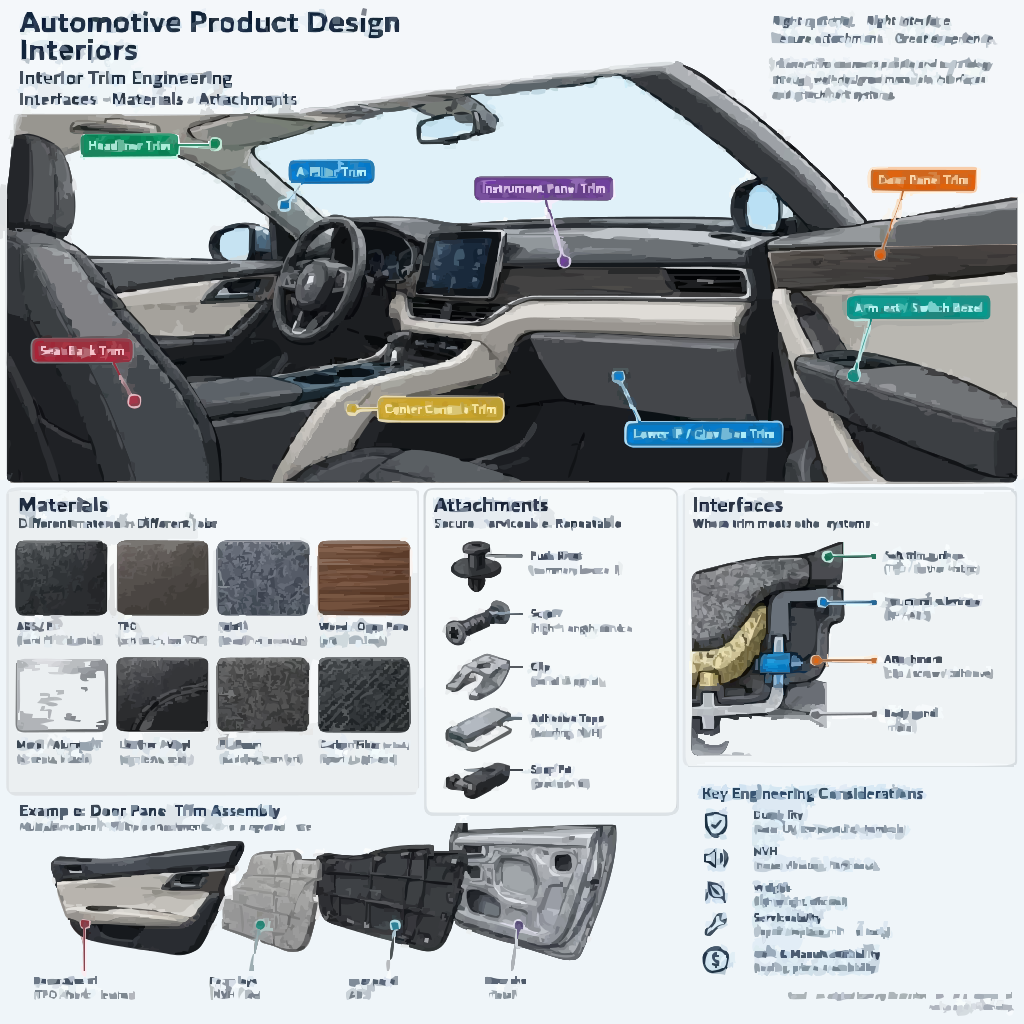
Interior components are studied as an interface network, not a parts list. Every visible edge, attachment point and service path is shared with a neighbouring system, which is why no interior part can be engineered in isolation.
| Interior assemblies, structural/functional role, and interfaces that constrain them | Interior assemblies, structural/functional role, and interfaces that constrain them | Interior assemblies, structural/functional role, and interfaces that constrain them |
|---|---|---|
| Assembly | Structural and Functional Role | Interfaces That Constrain It |
| Instrument panel and carrier | Appearance surfaces, HVAC distribution, restraint packaging, electrical content and service access; mounts to the cross-car beam | Body structure (BIW), cross-car beam, door trims at the A-pillar junction, windshield, restraint and electrical teams |
| Door trim | Substrate, armrest, pull handle, switch bezel, map pocket, speaker grille and retention | Door inner panel, water management provisions, side-airbag module, wiring harness, glass run channel, beltline seal |
| Centre console | Storage, cupholders, armrest, human-machine interface and electrical content | Floor tunnel, seat frames, rear HVAC distribution, harness routing |
| Pillar trims (A/B/C/D) | Cover structural pillars; integrate with curtain airbag envelope and head-impact requirements | Body pillars (BIW), headliner edge, weather seals, curtain airbag package, seat-belt adjuster on B-pillar |
| Headliner and overhead systems | Substrate and covering, roof attachment, sunroof and overhead console openings, acoustic function | Roof structure, sunroof frame, grab handles, lighting and sensor modules, curtain airbag |
| Floor and luggage trim | Carpet, load floor, parcel shelf and closeout panels | Underbody structure, seat mounting, load-space requirements, rear trim connections |
Working insight the programme insists on: the visible gap an occupant sees between two trims is produced by two different suppliers working to two different drawings, and it holds only when datum strategy and locating logic are consistent across both.
03 · OCCUPANT PACKAGING
Occupant Packaging and Ergonomics
Interior geometry is bounded by people before it is bounded by tooling. Packaging decisions fix component architecture, and architecture fixes what manufacturing must later achieve. See Packaging & Interfaces for the wider subject.
Packaging inputs applied in the programme:
Driver and passenger seating positions and the resulting H-point reference
Instrument panel and steering-column clearance envelopes
Knee, leg and headroom requirements, including overhead component clearance
Reach to switches, handles and controls across the intended occupant population
Visibility of displays, warning indicators and important controls
Entry and exit clearances
Seat adjustment and movement envelopes
Storage accessibility and contact comfort at armrests, door pads and grab handles
Clearance from moving mechanisms, pedals and seat structures
Ergonomic engineering translated into component decisions: a control that is unreachable is a packaging failure, not a styling preference; an armrest that loads a bracket beyond its section capacity is an ergonomic decision that becomes a structural problem.
Learners produce an occupant packaging review that identifies critical dimensions, functional envelopes, potential interference areas and interfaces requiring confirmation — the document that precedes component definition.
04 · PLASTIC COMPONENT ENGINEERING
Plastic Component Engineering
Most interior hard trim is moulded, and feature-level geometry decides whether the part succeeds. See Component Engineering for the fuller method.
Wall thickness and transitions. Uniform nominal section is the default because thickness change drives sink, warpage and residual stress. Where a transition is unavoidable it is stepped and radiused rather than abrupt. Thickness is set against flow length, structural demand and appearance class — not for modelling convenience.
Ribs and gussets. Ribs raise stiffness without adding mass, but a rib too thick relative to the nominal wall produces sink on the visible surface. Rib thickness is set against the sink rule; rib height, spacing and intersection patterns are reviewed for mould filling, air trapping and ejection. Gussets reduce stress concentration at corners and boss bases.
Bosses. Fastener bosses need stand-off from the nominal wall, a radiused base and often gussets, so screw torque and pull-out load are carried without cracking or surface read-through on the A-side. A boss on a visible surface is an appearance risk, not only a structural feature.
Draft. Draft is required for release, and the requirement increases on textured surfaces because the grain itself resists ejection. Draft strategy therefore interacts directly with appearance specification — a point learners initially treat as a tooling detail.
Clips, doghouses and attachment features. Engagement depth, insertion and release force, doghouse stiffness, local deformation, assembly access, tolerance variation and serviceability are all decided at feature level.
Defects that must be predicted at design stage
| Moulding defects, mechanisms and design responses | Moulding defects, mechanisms and design responses | Moulding defects, mechanisms and design responses |
|---|---|---|
| Defect | Mechanism | Design Response |
| Sink | Local mass cooling slower than surrounding wall | Reduce rib or boss section, stand the feature off the wall, relocate the fastening point |
| Warpage | Non-uniform shrinkage, cooling or residual stress | Balance wall sections, review gate position, adjust packing strategy |
| Weld or knit lines | Flow fronts meeting without full knitting | Reposition gates; keep knit lines away from visible and high-stress zones |
| Short shots | Cavity unable to fill | Review wall section and flow path; add or revise gating |
| Flash | Excess material escaping at parting lines or tool interfaces | Review tool shut-off design and clamp capability |
| Burn marks | Trapped gas or excessive local heating | Review venting and flow-front behaviour |
| Ejection marks | Component release before adequate stiffness or draft | Review ejector location and local stiffness |
| Scuffing | Insufficient draft against a textured surface | Increase local draft or revise texture depth |
Values are conditional, not universal. Wall thickness, rib-to-wall ratio and draft angle depend on material grade, component size, appearance class, tooling, moulding process and supplier capability. The programme teaches the reasoning and the verification route, and deliberately avoids presenting one supplier's practice as an industry rule.
05 · RETENTION & ASSEMBLY
Retention, Attachment and Assembly Logic
Interior quality is largely retention quality. A trim retained poorly rattles, gaps and loosens with use regardless of how well it is shaped.
| Retention methods, application logic and design prerequisites | Retention methods, application logic and design prerequisites | Retention methods, application logic and design prerequisites |
|---|---|---|
| Method | Application Logic | Design Prerequisite |
| Clips and push pins | Serviceable, high-volume attachment of trim to body | Correct engagement depth, doghouse strength, balanced insertion and release force |
| Doghouse and snap-fit | Integrated retention without separate fasteners | Section thickness at the flexing feature, draft, predictable release force |
| Screw bosses and threaded fasteners | Load-bearing or high-retention joints with service access | Boss stand-off, gusseting, torque and stripping capacity |
| Heat staking | Permanent retention of brackets and small components | Stake geometry, material compatibility, process control |
| Ultrasonic and vibration welding | Permanent joints on large assemblies and split lines | Joint design, material compatibility, process window and access — see Joining Technology |
| Adhesive and tape | Appearance-critical, sealing or multi-material interfaces | Surface preparation, bond-line control, heat and humidity durability |
Locating strategy. Position must be established before fasteners are driven. Locator pins and sockets, keyed orientations and asymmetric clip patterns set the part in place and stabilise gap and flush across suppliers. Error-proofing features — a clip that engages one way only, a locator that seats only in the correct orientation — reduce wrong assembly on the line. See DFA.
Assembly sequence. Interior modules build in a defined order because access closes up as content is added. Harness routing, airbag module installation, duct connection and final trim closure each impose precedence. A sequence that ignores access produces a module that cannot be built at line rate.
Serviceability. Critical modules — cluster, display, HVAC controls, airbag module, glove box — must be removable without destroying surrounding trim. Service access is a design requirement, not a convenience.
06 · APPEARANCE & PERCEIVED QUALITY
Appearance and Perceived Quality
Interior appearance is a dimensional and process discipline as much as a styling one.
Gap and flush between adjacent trims is the most visible quality indicator in the cabin, and it is produced by datum strategy, tolerance allocation and locator design — not by adjusting parts at the end of the line. See Tolerance Stack-Up.
Grain, gloss and colour consistency depend on tool finish, texture depth and direction, gate location and material lot behaviour. A gate placed where its flow disturbance is visible compromises the surface regardless of downstream finishing.
Parting lines are positioned to hide them from the occupant's typical viewing angle — a decision made at design stage, not at tool tryout.
Soft-touch and decorative systems — skins, foams, films, laminates, paint and bright finishes — introduce their own process windows and durability requirements and must be selected against touch, wear, UV exposure and cost.
Scratch, abrasion and chemical resistance are specified for surfaces the occupant contacts repeatedly, and drive both material and texture choice.
07 · SAFETY INTERFACES
Safety Interfaces — Awareness and Packaging
Interior engineers do not certify occupant safety, but they design the geometry that determines whether safety systems can function. The programme develops working awareness with an explicit boundary, not certification capability.
Airbag door and chute packaging. Passenger airbag deployment requires a scored door, a hinge concept and a chute path clear through the substrate. When a display or storage requirement grows, chute clearance is the first thing lost — and the consequence is a restraint-system conflict. Learners work through the packaging constraint and the coordination it requires.
Curtain airbag envelope. Pillar and headliner trims must leave the deployment path clear, and attachments must not obstruct it. A trim redesign that relocates a clip can invalidate the package.
Head-impact zones. Trim thickness, rib configuration, sharp-edge avoidance and attachment integrity in head-strike regions are constrained by regulation and internal targets.
Restraint under load. Interior attachments must retain components under deployment and occupant contact loads, so clip strength and doghouse integrity are safety-relevant, not merely quality-relevant.
Boundary. Safety-related design values and deployment requirements come from the applicable vehicle programme, regulation and authorised safety engineering process. A generic trim rule cannot substitute for that validation, and the programme states so explicitly.
08 · NOISE & STRUCTURAL FEEL
Noise: Squeak, Rattle and Structural Feel
Squeak and rattle are designed in or designed out at geometry level. Isolation materials compensate for residual risk; they do not correct a poor interface.
Mechanism-first sequence taught
Identify contact points. Every intentional and potential interface between mating components.
Classify the interface. Is contact intended, and is relative motion possible under vibration and thermal cycling?
Address the root cause first. Increase local stiffness, add a positive locating feature, or separate the surfaces so the interface is stable by design.
Apply isolation second. Felt, flocking, foam tape and soft clips where residual motion cannot be eliminated economically.
Verify. Confirm the fix addresses the mechanism rather than the symptom.
Common contributors: plastic-to-plastic and plastic-to-metal contact, loose clips and fasteners, insufficient local stiffness, incorrect clearances, dimensional variation, harness or duct contact, inadequate isolation, thermal expansion and wear.
Material pairing matters. Two components of the same material sliding against each other behave differently from dissimilar pairs, and this becomes a selection criterion alongside appearance and cost.
Structural feel issues addressed in the same logic: oil-canning of large unsupported panels under hand pressure, buzz from loosely retained components, and perceived stiffness of armrests and console lids — all governed by rib layout, attachment density and substrate section.
09 · DIMENSIONAL MANAGEMENT
Dimensional Management and Fit and Finish
Datum strategy must reflect assembly reality. The datum scheme defined on the drawing has to match the locating features used in the assembly fixture and the references used at inspection; where these diverge, dimensional disputes follow.
Tolerance stack-up is computed across the chain that governs the visible gap — substrate, attachment, soft trim, body structure and adjacent component. Worst-case and statistical methods are both applied, and the result sets the tolerance allocated to each contributor. See Tolerance Stack-Up and GD&T.
Critical characteristics identified from the stack-up are documented on the drawing, so suppliers and inspection focus on the dimensions that actually control appearance.
Fitment problem-solving approach: identify the visible or functional concern; establish the relevant interfaces; review locating and datum strategy; check the dimensional chain; identify component and assembly variation; evaluate clip and attachment behaviour; recommend a design or process correction; verify through suitable inspection.
10 · MATERIALS & SELECTION
Materials and Selection Logic
Material choice is argued against exposure and function rather than chosen by habit. See Materials Engineering for the broader subject.
| Interior material families, typical applications and selection considerations | Interior material families, typical applications and selection considerations | Interior material families, typical applications and selection considerations |
|---|---|---|
| Material Family | Typical Interior Application | Selection Consideration |
| PP and PP-based compounds | Door trim substrates, pillar trims, load-space trim | Weight and cost efficiency; grades tuned for stiffness and impact |
| ABS | Visible trim where surface and dimensional quality matter | Impact, temperature and appearance requirements drive grade |
| PC/ABS | IP components and visible parts requiring heat and impact balance | Selected against thermal load and surface specification |
| PA | Selected functional and structural features | Moisture absorption and dimensional behaviour must be managed |
| TPE / TPO | Soft-touch and flexible surfaces | Surface feel, durability and process route |
| Foams, fabrics, laminates | Headliner covering, armrests, soft trim | Adhesion, ageing, appearance and environmental performance |
Selection criteria applied: mechanical strength and stiffness; impact performance; heat resistance; dimensional stability; scratch and abrasion resistance; UV and colour stability; chemical resistance; odour and fogging requirements; surface texture and gloss; recyclability; and cost against manufacturing feasibility.
The working distinction: a sun-exposed upper instrument panel surface and a concealed bracket are not the same material decision, and the reasoning must be stateable in review.
11 · MOULDING DFM METHOD
Manufacturing DFM Review Method
The programme teaches a repeatable review sequence, applied to every project — the same discipline as the DFM method for other plastics domains:
Establish component function, appearance class and structural demand.
Confirm material against exposure, impact, heat, scratch and UV requirements.
Review wall-thickness strategy and identify abrupt transitions.
Review rib, boss, gusset and doghouse geometry against sink and stress rules.
Check draft on textured and polished surfaces.
Examine gate location against appearance, weld-line placement and packing.
Identify undercuts and side actions and justify or eliminate them against tooling cost and complexity.
Confirm moulding direction, tool separation, parting-line placement and ejection.
Record risks and recommend geometry or process changes with justification.
Processes beyond injection moulding are covered where interior components require them: thermoforming and compression moulding for headliners, foam moulding for soft-touch parts, lamination and bonding for covered surfaces, heat staking and ultrasonic or vibration welding for assemblies, and cutting and trimming for finishing operations. See Manufacturing Processes.
The output is a written DFM assessment — a technical position with identified risks and recommendations, not a checklist of ticked boxes.
12 · RISK, VALIDATION & CHANGE
Risk, Validation and Change Control
DFMEA. Identify failure modes across the subsystem — clip breakage in assembly, retention loss in service, sink marks on visible surfaces, warpage affecting fitment, squeak and rattle at contact interfaces, boss cracking, airbag packaging conflict, thermal deformation, surface deterioration — assess severity, occurrence and detection, and convert the highest risks into design actions. The link from failure mode to action is what separates a working DFMEA from one completed for audit.
DVP&R. Each requirement and each significant risk maps to a verification method, acceptance criterion and result record. Where a test does not exercise the identified failure mode, the test is corrected rather than retained for completeness.
| Validation categories and typical scope | Validation categories and typical scope |
|---|---|
| Validation Category | Typical Scope |
| Dimensional | Component dimensions, interface fitment, gap and flush, clip and mounting-hole position |
| Mechanical | Clip retention and pull-off, fastener and attachment strength, armrest and grab-handle requirements, local stiffness |
| Environmental | Heat ageing, thermal cycling, UV exposure, humidity, chemical resistance |
| Surface and appearance | Scratch and abrasion resistance, colour consistency, grain and texture matching, gloss, odour and fogging as specified |
| NVH | Squeak and rattle evaluation, vibration-related contact checks, retention and isolation assessment |
| Safety-related | Head-impact assessment and airbag deployment compatibility within the authorised programme process |
ECR/ECN discipline. A change to a trim component rarely affects one part. Appearance, adjacent interfaces, tooling, airbag packaging, harness routing and supplier documentation may all move with it. Learners process a change through request, impact assessment across affected systems, approval and controlled release with revision traceability. Terminology varies between organisations — ECR, ECN, ECO, DCR — so the control principle is taught rather than one organisation's form.
Development phase awareness. Learners understand what design contributes at each stage — requirement analysis, packaging, architecture, concept and material selection, component engineering, DFM/DFA, dimensional engineering, risk assessment, verification planning and controlled release — and why a change that skips a phase gate tends to surface as a launch problem. See APQP & PPAP.
13 · PROJECT WORK
Project Work and Portfolio Evidence
Projects are engineering exercises with a written position at the end. They are representative learning studies, not confidential OEM programmes.
| Interior projects, decisions defended and portfolio evidence | Interior projects, decisions defended and portfolio evidence | Interior projects, decisions defended and portfolio evidence |
|---|---|---|
| Project | Decisions the Learner Defends | Portfolio Evidence |
| Door trim module | Substrate stiffness against oil-canning and map-pocket loads; clip and doghouse strategy against insertion force; speaker and switch packaging against visible surface quality; water management without blocking service access; armrest load path through bracket, gusset or integrated rib | Component breakdown, retention and doghouse assessment, plastic DFM review, DFA sequence, dimensional considerations |
| Instrument panel sub-assembly | Carrier stiffness against NVH and airbag reaction loads; mounting to the cross-car beam and its effect on gap and flush to door trims; chute clearance under a display packaging conflict; defroster and duct sealing against leakage and rattle; service access without visible fasteners | Interface and packaging study, airbag-path awareness note, duct sealing reasoning, appearance feasibility review |
| Centre console | Structure and storage layout; armrest interface and load path; locator strategy against the floor tunnel; assembly sequence with the floor environment; interface stability against squeak | Architecture study, attachment strategy, DFA sequence, squeak and rattle risk assessment |
| Pillar trim feasibility | Attachment point strategy against the curtain airbag envelope; head-impact thickness and sharp-edge considerations; headliner and seal interfaces; belt and adjuster interfaces on B-pillar; visible-edge dimensional control | Feasibility report, retention and airbag-path review, dimensional control note, risk summary |
| Headliner and overhead study | Substrate construction and shape retention; covering and lamination route; roof attachment and opening accuracy; grab-handle and lighting retention; fit with pillar trims and seals | Substrate and process comparison, attachment review, fitment and appearance assessment |
| Plastic DFM case study | Wall thickness and rib strategy; boss stand-off against sink; draft on textured surfaces; gate location against appearance and weld-line placement; undercut elimination against tooling cost | DFM report, defect-risk register, recommended geometry changes with justification |
| Change case (ECR to ECN) | Scope of impact across affected trims and systems; tooling and validation consequences; revision and effectivity control | Change request, impact assessment, controlled release record |
Assessment weighs technical correctness, reasoning quality, documentation discipline and defensibility under questioning. Work that cannot survive review questioning is reworked rather than passed.
14 · COURSE OUTCOMES
Course Outcomes
What a learner can demonstrate at the end of the interior domain, across packaging, plastic engineering, retention, dimension, NVH and change.
| Interior outcome areas and learner capability | Interior outcome areas and learner capability |
|---|---|
| Outcome Area | Learner Can Demonstrate |
| Cabin architecture | Explain interior system interfaces and the constraints each assembly imposes on its neighbours |
| Occupant packaging and ergonomics | Read packaging envelopes, identify clearance and interference risks, and relate ergonomic requirements to component layout |
| Plastic component engineering | Set wall thickness, rib, boss, gusset and draft strategy with sink, warpage and weld-line risk identified in advance |
| Material selection | Select polymer and soft-trim families against appearance, impact, heat, scratch, UV and processing requirements with stated reasoning |
| DFM assessment | Conduct a structured moulding feasibility review and produce a defensible written position |
| DFA and retention | Compare attachment methods, design locating and error-proofing features, and sequence a module build |
| Fit and finish | Establish a functional datum scheme, apply GD&T, and compute stack-up across substrate, soft trim and body |
| Perceived quality | Control gap, flush, grain, gloss, colour and parting-line outcomes through design decisions |
| NVH | Identify squeak and rattle mechanisms and address them through geometry and stiffness before isolation |
| Safety interfaces | Recognise airbag and head-impact packaging constraints and coordinate the geometry they require, within the programme's stated boundary |
| Risk and validation | Structure a DFMEA, link failure modes to verification activity, and map requirements to validation categories |
| Change control | Assess change impact across affected systems and control release with traceability (ECR/ECN) |
| Technical communication | Present and defend interior engineering decisions in a review setting |
These outcomes represent learning capability. Independent performance in a live programme also depends on workplace exposure, programme-specific requirements and employer expectations.
15 · CAREER OUTCOMES
Job Opportunities
Roles this interior domain supports, and what the work typically involves.
| Interior roles and typical work | Interior roles and typical work |
|---|---|
| Role | What the Work Involves |
| Interior Trim Engineer | Component ownership across IP, door trim, console and pillar trims from concept to release |
| Plastic Component Engineer | Feature-level engineering of ribs, bosses, doghouses, brackets and attachments |
| Instrument Panel Engineer | IP architecture, cross-car beam mounting, HVAC and electrical packaging, appearance and dimensional quality |
| Door Trim Engineer | Substrate, armrest, speaker and switch interfaces, retention and door-system integration |
| Interior Product Engineer | Multi-attribute coordination across appearance, safety, NVH and manufacturing |
| Design Release Engineer | Development phase gates, production approval evidence and change control across the interior release cycle (APQP/PPAP) |
| Interior DFM / Manufacturing Engineer | Moulding feasibility, tooling concerns, assembly methods and manufacturing quality |
| Interior Dimensional Engineer | Datum strategy, GD&T, tolerance stack-up, fitment and variation control |
| Interior Validation Engineer | Fit checks, retention and pull-off testing, environmental exposure and squeak and rattle evaluation (DVP&R) |
Employer types: passenger vehicle OEMs, two-wheeler manufacturers, Tier-1 interior and trim suppliers, cockpit and seating module suppliers, engineering R&D service providers, and EV manufacturers designing new cabin architectures.
Job titles and responsibilities vary by company. Some positions also require specialist analysis capability, PLM experience or prior programme exposure; candidates should verify requirements in the specific job description.
17 · WHO SHOULD TAKE THIS DOMAIN
Who Should Take This Domain
This interior domain suits learners building a plastics and cabin-systems specialisation, or moving into design from adjacent functions.
Mechanical and automobile engineering students building an interior specialisation before final-year placements — start with Automotive Fundamentals.
Production and manufacturing graduates moving from process execution toward design-side feasibility.
Diploma and technical-training holders strengthening plastic component and drawing knowledge.
Engineers already in BIW, exterior plastics or seating who need interior literacy to own cross-cabin interfaces.
Working professionals who already model interior components but have never owned the manufacturing, assembly or dimensional justification behind them.
Career-restart engineers refreshing fundamentals and current development methods.
Assumed foundation: engineering drawing interpretation, basic mechanical engineering, material properties, manufacturing process fundamentals, basic engineering mathematics, and understanding of dimensions and tolerances. Prior interior domain experience is not required.
18 · FREQUENTLY ASKED QUESTIONS
Frequently Asked Questions
1. How are sink marks actually prevented on a visible dashboard surface?
2. What is the real difference between interior styling and interior engineering?
3. I keep hearing wall thickness and draft angle values quoted as rules. How should I treat them?
4. Why do two suppliers' trims still produce a visible gap mismatch when both parts meet their own drawings?
5. Why is squeak and rattle treated as an engineering problem rather than a quality fix?
6. Do I need to know airbag regulations to work in interiors?
7. Are EV cabins engineered differently from combustion-engine cabins?
8. Which interior projects should a fresher put in a portfolio?
9. I work in production or quality at a Tier-1 interior supplier. Is a move into design realistic?
10. How do interviewers test interior engineering knowledge in technical rounds?
CONTINUE LEARNING
Explore Related Domains & Methods
Interior engineering sits at the intersection of every cabin system and applies every product-development method. Continue into the related pages below.
BIW EngineeringClosures EngineeringExterior Product EngineeringSeating EngineeringEV EngineeringLighting EngineeringComponent EngineeringMaterials EngineeringManufacturing ProcessesJoining TechnologyPackaging & InterfacesGD&T TrainingTolerance Stack-UpDFMDFADFMEADVP&RAPQP & PPAPECR & ECNQuality EngineeringDocumentation & ReviewsCase StudiesPractical AssignmentsInterview Preparation
COMPONENT ENGINEERING DEEP DIVE
A-pillar trim: occupant interface, retention and polymer design
Educational schematic for engineering discussion. Not an OEM-released drawing or vehicle-specific design.
Component: A-pillar trim. A cabin trim component that covers the pillar structure and integrates with the windshield edge, instrument panel, headliner and adjacent interior parts. Its design is strongly affected by occupant protection and airbag packaging.
| Engineering lens | What the engineer must evaluate |
|---|---|
| Function and structure | Review occupant contact surfaces, edge radii, visibility, trim retention and compatibility with the curtain-airbag deployment path where fitted. Attachment features must not obstruct or delay the intended restraint-system function. |
| Material selection | Select the polymer and texture/finish based on impact behaviour, heat ageing, flammability requirements, colour stability, emissions/odour requirements and mouldability specified for the programme. |
| Manufacturing, joining and assembly | Injection-moulding checks include draft, nominal wall strategy, ribs, bosses, local thickness transitions, gate/weld-line locations, shrinkage, warpage, ejection and tool split. Clip and tether features require retention, assembly and service review. |
| Packaging and dimensional control | Map interfaces to pillar structure, windshield reveal, instrument panel, headliner, weatherstrip and restraint system. Confirm tolerance accumulation, squeak/rattle paths, service access and controlled attachment points. |
| Quality, risk and validation | DFMEA should include clip fracture/disengagement, rattle, visible mismatch, warpage and interference with safety-system packaging. Validation must follow the applicable occupant-safety, durability, environmental and customer requirements. |
Expected engineering output
Prepare a component function statement, interface register, material/process rationale, DFM/DFA review, critical-feature and datum rationale, risk assessment, verification outline and change-impact checklist. State all assumptions and trace every acceptance criterion to an authorised requirement.
Build your automotive engineering knowledge
Explore the technical subjects or contact MYTECHLEARN about your learning objectives.
Enquire Now
PRACTICAL OUTPUT
Sample Interior Product Engineering Deliverables
Learners produce assessed engineering work that demonstrates decision-making expected in product development roles:
Component identification and functional analysis of a trim assembly
Plastic construction, wall section and feature guideline review
Clip, doghouse and attachment strategy assessment
Packaging, clearance and interface study
Gap, flush and tolerance considerations
DFM/DFA and moulding feasibility notes
Potential failure and validation focus areas
Engineering review report with recommendations
Practical Application
Examples are educational training aids. They illustrate technical judgement required in OEM and Tier-1 environments and are not OEM-released designs.