
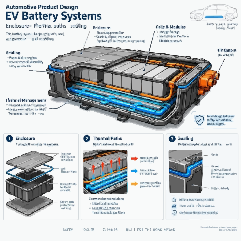
EV Engineering Training — Battery Systems, Structures and Thermal Integration
EV product engineering training across battery enclosures, thermal packaging, sealing, HV packaging awareness, large-part DFM, GD&T stack-up and ECR/ECN control. Build production-ready EV structural competence for OEM, pack manufacturer and Tier-1 roles — with emphasis on engineering decisions and production readiness.
Enquire About EV TrainingRequest Domain Curriculum
01 · WHAT EV ENGINEERING DECIDES
What EV Engineering Actually Decides
An electric vehicle is not a combustion vehicle with the engine removed. Removing the engine and fuel system removes the structure that used to absorb front-end energy, the mass distribution that set the handling balance, and the noise floor that hid squeaks and rattles. What replaces them is a large, heavy, high-voltage, thermally active structure mounted under the floor — and that structure becomes the central mechanical engineering problem of the vehicle.
The battery pack is not a component bolted into a car. It is a load-bearing element of the underbody that must survive side pole impact and road debris, hold an environmental seal for the life of the vehicle, carry coolant without leaking, maintain high-voltage separation, contain a thermal event if one occurs, and be removable for service. Every one of those requirements is a mechanical engineering decision, and each constrains the others.
This domain trains those decisions: pack architecture, enclosure construction, battery-to-body mounting, thermal packaging, sealing logic, large-part dimensional control, joining of dissimilar materials, and controlled engineering change. Learners are assessed on whether their decisions hold together under review questioning — not on how a model renders.
02 · WHAT CHANGES FROM ICE
What Changes from a Combustion Vehicle
| Engineering differences between combustion vehicles and electric vehicles | Engineering differences between combustion vehicles and electric vehicles | Engineering differences between combustion vehicles and electric vehicles | Engineering differences between combustion vehicles and electric vehicles |
|---|---|---|---|
| Engineering Area | Combustion Vehicle | Electric Vehicle | New Decision the Engineer Must Make |
| Primary energy storage | Fuel tank, low mass, irregular packaging | Traction battery, high mass, large flat footprint | How to distribute pack mass and mount it into the underbody |
| Propulsion | Engine and multi-ratio transmission | Motor and single-speed reduction drive | How to package drive-unit torque reaction into the subframe |
| Underbody | Exhaust routing, fuel lines, floor structure | Battery enclosure and protection structure | How to make the enclosure part of the load path |
| Thermal management | Engine and cabin cooling | Battery, motor, inverter and cabin thermal systems | How to route coolant to the pack without creating leak paths |
| Electrical architecture | 12 V conventional | High-voltage traction plus low-voltage systems | How to preserve HV clearances and service safety in mechanical geometry |
| Crash behaviour | Front structure absorbs energy | Front structure still absorbs, but the pack must not be breached | How to protect cells from side and underbody intrusion |
| Noise floor | Engine masks noise | Quiet powertrain exposes squeak and rattle | How to design interfaces that stay quiet |
The recurring theme: EV engineering adds structural, sealing and thermal obligations to parts that would previously have been simple covers or shields. The programme is built around that shift.
03 · SYSTEM ARCHITECTURE
System Architecture and Interface Map
| EV systems, mechanical engineering roles and interfaces | EV systems, mechanical engineering roles and interfaces | EV systems, mechanical engineering roles and interfaces |
|---|---|---|
| System | Mechanical Engineering Role | Interfaces That Constrain It |
| Battery pack and enclosure | Structural housing, cell and module retention, sealing, thermal contact, HV separation | Underbody structure, rockers, floor cross-members, cooling circuit, HV harness, service access |
| Battery-to-body mounting | Load transfer into the body, dimensional alignment, isolation | BIW floor, rocker and sill structures, front and rear mounting arrangements |
| Electric drive unit | Motor and reduction gear packaging, torque reaction, mounting | Subframe, driveshafts, cooling circuit, HV connections |
| Thermal management | Cooling plates, coolant manifolds, hoses, heat exchangers, chiller interfaces | Pack interior, front-end heat exchangers, cabin HVAC, service access |
| HV distribution | Busbars, connectors, service disconnect, cable routing | Enclosure penetrations, clearances, service procedures |
| Underbody protection | Skid plates, shields, deflectors, aerodynamic closeouts | Pack base, ground clearance, impact protection, corrosion |
| Charging interface | Inlet packaging, on-board charger and DC-DC packaging | Body side or front-end, harness routing, thermal management |
Working insight the programme insists on: the enclosure is simultaneously a structural member, a pressure boundary, a thermal component and an electrical containment. A decision taken for one of those functions is almost always felt by the other three.
04 · PACK CONSTRUCTION
Battery Pack Construction
Learners study the pack as a layered system rather than a single assembly.
Cell formats. Cylindrical, prismatic and pouch cells differ in energy density, packaging efficiency, retention requirements, thermal contact geometry and serviceability. The format choice propagates directly into the enclosure design — a pouch cell pack and a cylindrical cell pack do not share the same retention, cooling or venting logic.
Cell-to-module-to-pack versus cell-to-pack. Module-based construction allows replacement, handling and thermal isolation at module level, at the cost of mass and volume. Cell-to-pack removes that intermediate structure to gain density but shifts structural and thermal responsibility onto the pack and enclosure and constrains serviceability. This trade-off is examined directly, because it drives almost every subsequent enclosure decision.
Structural elements inside the pack: module frames and internal supports, cross-members and partitions, cell retention features, and the mounting interface between the internal structure and the enclosure base.
Electrical interfaces that become mechanical constraints: busbar routing and support, BMS sensor mounting, connector positioning, and the service disconnect access route. Busbars must be supported against vibration, separated from structure to preserve clearance, and accessible where the service procedure requires it.
Service access and assembly sequence. A pack that cannot be opened, diagnosed or partially serviced without destroying its seal is a maintenance liability. Assembly and disassembly sequence is a design output, not a plant detail. See DFA.
05 · ENCLOSURE ENGINEERING
Enclosure Engineering
The enclosure is the most consequential mechanical component in the pack, and it carries several responsibilities at once.
| Enclosure responsibilities and engineering questions | Enclosure responsibilities and engineering questions |
|---|---|
| Responsibility | Engineering Question the Learner Must Answer |
| Structural | What stiffness and strength does the enclosure provide, and what load path does it create in the vehicle? |
| Cell protection | Can the base and sides resist underbody strike and side intrusion without breaching the cells? |
| Sealing | Can a continuous seal be maintained across a long flange, through thermal cycling and vibration, for the vehicle's life? |
| Thermal | Does the enclosure support cooling-plate contact and allow thermal interfaces to be maintained under compression? |
| HV containment | Does internal geometry preserve clearances and prevent contact with live components? |
| Serviceability | Can the pack be installed, removed and serviced within the available access? |
| Manufacturing | Can the tray and cover be produced and assembled repeatably at volume? |
Tray and cover construction. A common architecture is a structural tray with the base plate, side walls and internal cross-members carrying load, closed by a cover that provides environmental protection rather than primary structure. This division of responsibility determines material, thickness and joining strategy — and it is why learners are asked to state which element carries which load before selecting a process.
Base plate and reinforcement. The base plate is the component most exposed to road debris and underbody strike, and it is where the enclosure's structural contribution is often concentrated. Reinforcement patterns, thickness and material must be argued against both impact protection and mass.
Cross-members and internal partitions. Internal structure supports modules, maintains the enclosure's cross-section, and can be arranged to divide the pack into zones that limit the spread of a thermal event. This is packaging with a safety function, and it is examined as such.
Flange and sealing geometry. The perimeter flange is where structural, sealing and manufacturing requirements meet most sharply. Flange flatness, width, bolt spacing, gasket compression and joint stiffness must all be consistent, and the flange must survive tooling, handling and assembly without distorting.
Drainage, venting and pressure management. Water that enters must be able to leave, and pressure differences across the enclosure must be equalised in a controlled way rather than through the seal. Venting and pressure-relief provisions are designed, not added.
Corrosion protection at dissimilar joints. An aluminium enclosure mounted to a steel body creates a galvanic couple. Coating, isolation, fastener selection and drainage are all design decisions that determine whether the joint survives the vehicle's life. See Materials Engineering and Joining Technology.
06 · STRUCTURAL INTEGRATION
Battery-to-Body Structural Integration
The mounting interface is where the pack becomes part of the vehicle, and where most integration disputes occur.
Load paths. The programme requires learners to trace how pack mass and dynamic loads are carried into the body, and what happens under front, rear and side impact. Mounting points placed purely for packaging convenience often produce load paths that concentrate stress in the rocker or the floor cross-member. See BIW Engineering.
Mounting arrangements. Front, rear and side mounting strategies differ in how they accommodate tolerance, thermal movement, crash behaviour and removal. Rigid mounting at every point constrains expansion and loads the fasteners; under-constrained mounting allows relative movement that damages seals and connectors. The arrangement must be argued, not assumed.
Fasteners and isolators. Bolt sizing, isolator selection, torque strategy and access for tooling are all part of the interface. Isolation also has an NVH function, which interacts with the structural requirement.
Rocker and sill integration. In many architectures the rocker is the primary barrier between a side impact and the pack. Its section, reinforcement and connection to the floor cross-members determine whether the pack is protected — and this is a BIW decision with an EV consequence, which is why the two domains must be coordinated.
Ground clearance and underbody protection. Clearance targets, skid plate strategy and shield attachment all affect the enclosure base and the vehicle's aerodynamic behaviour.
Pack removal and installation. Service strategy constrains the mounting design: a pack that requires subframe removal for service changes the whole vehicle's service economics.
Dimensional alignment. Mounting hole positions across the body and the pack are a tolerance chain. Misalignment at assembly is a dimensional engineering failure, not a build-quality complaint.
07 · THERMAL MANAGEMENT
Thermal Management Packaging
Thermal management is taught from the mechanical packaging side: what has to be held, routed, compressed and accessed.
Cooling plate and cold plate arrangement. The cooling plate must make contact with the cells or modules through a defined thermal interface while the enclosure carries structural load. These two requirements compete for the same space and the same flatness.
Thermal interface materials. The interface between the cooling plate and the cell or module surface is maintained by controlled compression. Too little compression and thermal performance drops; too much and the cells or the plate are loaded structurally. Compression is therefore a dimensional requirement, and it is governed by the same stack-up discipline as any other joint.
Coolant routing, hoses and connectors. Routing must avoid strain at fittings, provide service access, keep the circuit clear of structural movement, and allow assembly without inducing preload. Hose routing that ignores assembly sequence produces leaks at the plant. See Packaging & Interfaces and DFA.
Manifolds and distribution. Coolant manifolds distribute flow across the pack. Their packaging determines whether flow is balanced and whether the circuit can be serviced.
Leak prevention as a design outcome. Every joint in the coolant circuit is a potential leak path into a high-voltage enclosure. Learners evaluate fitting type, joint access, sealing strategy and validation implications together. See Joining Technology.
Preconditioning and thermal interfaces with the rest of the vehicle. Battery thermal behaviour is coupled to cabin HVAC, motor and inverter cooling, and charging. The exterior and underbody interfaces this creates are part of the packaging problem.
08 · SEALING & IP
Sealing and Ingress Protection Logic
Sealing is treated as a dimensional and structural problem, not a gasket specification.
How the seal actually works. A continuous gasket is compressed between two flanges by a bolted joint. The seal holds only if compression is maintained uniformly around the entire perimeter — which requires flange flatness, adequate flange stiffness, correctly spaced fasteners, and a gasket that tolerates the compression range it will actually see.
Why seals fail in practice. Perimeter flange distortion after welding or machining; insufficient flange stiffness allowing the joint to open under pressure or load; bolt spacing too wide to maintain compression between fasteners; thermal expansion differences between the tray and cover materials; gasket compression set over time; and damage to the sealing surface during handling or assembly.
Dimensional control of the sealing joint. Flange flatness, bolt-hole position and gasket groove geometry form a stack-up that determines whether compression stays in range. This is where GD&T meets the pack, and the programme treats it as a worked calculation rather than a statement. See Tolerance Stack-Up.
Ingress protection awareness. IP ratings define protection against dust and water ingress, and the applicable rating and test method come from the vehicle programme and the relevant standard. The engineer's job is to design a joint that can pass the test repeatedly in production, not to assume that a gasket selection achieves a rating.
Venting. A sealed enclosure that cannot equalise pressure will load its own seal as altitude and temperature change. Pressure-equalisation devices are a design requirement, and their placement must not create a water path.
09 · HIGH-VOLTAGE PACKAGING
High-Voltage Packaging — Awareness and Boundary
Mechanical engineers design the geometry that determines whether high-voltage systems remain safe. They do not own the electrical design.
What the mechanical engineer must preserve: clearance and creepage distances between live parts and structure, insulation boundaries, busbar support and separation, connector mounting and access, service disconnect accessibility, and the routing envelope for HV cabling including bend radius and strain relief.
Where decisions must defer. Electrical isolation design, insulation coordination, HV safety procedures and live-system servicing belong to qualified electrical and safety specialists and to the authorised vehicle programme. Mechanical geometry that intrudes on a clearance is a design defect, but the clearance value itself is not a mechanical engineer's judgement call. The programme states this boundary explicitly rather than implying the training qualifies anyone for HV work. This protects both the learner and the credibility of the content with OEM reviewers.
10 · MATERIALS & JOINING
Materials and Joining for EV Structures
Material families are compared on engineering grounds — stiffness-to-mass, process feasibility, joining compatibility, corrosion risk and cost. See Materials Engineering for the broader subject.
| EV material routes and engineering considerations | EV material routes and engineering considerations | EV material routes and engineering considerations |
|---|---|---|
| Material Route | Typical EV Application | Engineering Consideration |
| Aluminium extrusions | Side frames, cross-members, structural rails | Good stiffness-to-mass; extrusion dies constrain section geometry; joining and galvanic isolation must be designed |
| Aluminium die-casting | Complex tray geometry, integrated mounting bosses, end structures | Consolidates parts; casting porosity and wall-thickness limits constrain design |
| Stamped steel | Trays, covers, reinforcement, skid plates | Established process and cost position; mass penalty against aluminium |
| High-strength and advanced high-strength steel | Body-side protection, rocker reinforcement, intrusion resistance | Higher strength with reduced forming window and springback sensitivity |
| Engineering plastics and composites | Covers, shields, selected non-structural components | Mass and corrosion advantages; structural and thermal limits must be respected |
Joining methods and the constraints each brings (see Joining Technology):
| Joining methods for EV structures and design prerequisites | Joining methods for EV structures and design prerequisites | Joining methods for EV structures and design prerequisites |
|---|---|---|
| Method | Use in EV Structures | Design Prerequisite |
| Friction stir welding | Leak-tight aluminium joints, cooling plates, extrusion assembly | Solid-state process; joint design and tool access must suit the method |
| MIG and TIG welding | Structural aluminium and steel fabrication | Distortion control and heat-affected zone consideration |
| Structural adhesive | Mixed-material joints, stiffness and sealing contribution | Surface preparation, bond-line control, curing and durability |
| Self-piercing riveting | Aluminium-to-steel and mixed-material joints | Material stack compatibility and tool access from both sides |
| Resistance spot welding | Steel-to-steel joints where applicable | Flange width, weld pitch and gun access |
| Mechanical fastening | Serviceable joints, mounting interfaces | Boss or insert capacity, torque strategy, galvanic isolation |
Galvanic corrosion is treated as a first-order design constraint, not a finishing detail. Where aluminium meets steel, the joint requires isolation, coating strategy, drainage and fastener selection decided together. See Materials Engineering.
11 · DIMENSIONAL CONTROL
Large-Part Dimensional Control
An enclosure is a large part with a sealing requirement, which makes dimensional control unusually demanding.
Datum strategy. The datum scheme must reflect how the pack is located in the body and how the sealing flange is inspected. If the drawing datum and the assembly locating scheme disagree, the seal will be compressed unevenly in production and the stack-up will not explain it. See GD&T.
Tolerance stack-up across the sealing joint and mounting interface. Worst-case and statistical (RSS) methods are both applied to the chain that governs gasket compression and to the chain that governs mounting-hole alignment. Learners compute both and judge whether the design target is achievable with the process capability available. See Tolerance Stack-Up.
Flatness and distortion in large parts. Welding, casting and machining all introduce distortion across a long flange. The design must tolerate the distortion the process actually produces, or the process must be changed — and the engineer has to make that argument with numbers. See Manufacturing Processes.
Critical characteristics. Dimensions identified from the stack-up are documented on the drawing so that inspection focuses on what actually controls sealing and mounting.
Required tolerance values come from the OEM drawing, the functional requirement and demonstrated manufacturing capability. The programme teaches the method and the reasoning, not a set of numbers.
12 · RISK, VALIDATION & STANDARDS
Risk, Validation and Standards Awareness
DFMEA. Identify failure modes across the pack — seal leakage, gasket compression loss, coolant leak into the enclosure, mounting fastener loosening, flange distortion, busbar contact with structure, enclosure breach under underbody strike, thermal interface degradation, vent blockage, galvanic corrosion at mixed-material joints — assess severity, occurrence and detection, and convert the highest risks into design actions.
DVP&R. Each requirement and each significant risk maps to a verification method, acceptance criterion and result record. Typical verification areas: structural strength and stiffness, vibration and shock, fatigue and durability, enclosure deformation and underbody impact protection, thermal cycling and thermal interface performance, coolant leakage and pressure testing, water and dust ingress, corrosion and environmental durability, and electrical isolation validation.
Why the linkage matters. A failure mode without a corresponding verification activity is an unmanaged risk. Learners are required to close that loop rather than list tests and failure modes in separate documents.
Standards awareness, with an explicit boundary. Learners are introduced to the framework within which EV programmes operate — including the ISO 6469 series for electrically propelled road vehicle safety, UN Regulation No. 100 for electric powertrain safety, the ISO 12405 series for traction battery testing within its applicable scope, IEC 60529 for ingress protection classification, Indian AIS requirements applicable to electric vehicles and their energy storage systems, IATF 16949 for automotive quality management, ASME Y14.5 for GD&T and AIAG-VDA methodology for FMEA.
Applicability depends on vehicle category, product scope, target market and the current revision of each document. Standards are not interchangeable and are revised. The programme teaches awareness and design implications; certification, testing and homologation remain with authorised organisations and accredited facilities.
Scope boundary retained throughout. Crash simulation, thermal-runaway propagation modelling, HV electrical design and battery chemistry are specialist disciplines. This programme develops the mechanical design understanding that interfaces with them — it does not deliver those capabilities.
13 · CHANGE CONTROL
Change Control on a High-Consequence Component
An engineering change on a battery enclosure is rarely local. A flange revision can move seal compression, mounting interfaces, coolant routing, HV clearances, tooling, validation status and supplier documentation at the same time. See ECR/ECN.
Learners process a change through request, impact assessment across affected systems, approval and controlled release with revision traceability. The impact assessment must cover:
Functional and structural effect
Sealing and ingress implications
Thermal interface consequences
HV clearance implications
Manufacturing and tooling impact
Validation and revalidation needs
BOM and drawing revision
Service and production timing
Terminology varies between organisations — ECR, ECN, DCR, ECO — so the control principle is taught rather than one organisation's form. What does not vary is the discipline: propose, assess, approve, implement, trace. See APQP & PPAP for development-phase awareness.
14 · PROJECT WORK
Project Work and Portfolio Evidence
Projects are engineering exercises with a written position at the end. They are representative learning studies, not confidential OEM programmes, and not certified designs.
| EV projects, decisions defended and portfolio evidence | EV projects, decisions defended and portfolio evidence | EV projects, decisions defended and portfolio evidence |
|---|---|---|
| Project | Decisions the Learner Defends | Portfolio Evidence |
| Battery enclosure engineering | Tray and cover division of structural responsibility; material and process route against stiffness, mass and manufacturing feasibility; reinforcement against underbody strike; flange and gasket geometry; drainage, venting and corrosion strategy | Requirement sheet, component breakdown, material justification, process selection, structural design note, sealing and joining strategy, DFM/DFA assessment, DFMEA extract |
| Battery-to-body integration | Mounting arrangement against load path, tolerance and removal; rocker and cross-member coordination; isolator and fastener selection; ground clearance and protection | Interface matrix, mounting arrangement study, load-path explanation, mounting tolerance analysis, assembly feasibility review |
| Thermal management packaging | Cooling plate arrangement and contact; thermal interface compression as a dimensional requirement; coolant routing without fitting strain; manifold distribution; service access | Thermal component map, cooling interface study, packaging and routing assessment, serviceability review, failure-risk assessment |
| Underbody protection and lightweighting | Impact protection concept against mass; material and thickness comparison; attachment and joining; corrosion and durability | Protection concept study, material comparison, manufacturing feasibility report, weight and cost trade-off, DFM/DFA review |
| Large-part dimensional study | Datum scheme against assembly and inspection reality; stack-up for gasket compression and mounting alignment; flatness and distortion allowance; critical characteristics selection | Worked stack-up sheet, dimensional study, recommended characteristic list |
| Sealing failure investigation and change | Root cause rather than symptom; DFMEA update; corrective design action; validation plan; controlled release | Problem statement, root cause analysis, DFMEA extract, corrective action report, DVP&R recommendation, ECR/ECN documentation |
Assessment weighs technical correctness, reasoning quality, documentation discipline and defensibility under questioning. Work that cannot survive review questioning is reworked rather than passed.
15 · COURSE OUTCOMES
Course Outcomes
What a learner can demonstrate at the end of the EV domain, across architecture, enclosure, thermal, sealing, HV packaging awareness and change.
| EV outcome areas and learner capability | EV outcome areas and learner capability |
|---|---|
| Outcome Area | Learner Can Demonstrate |
| EV architecture | Explain EV system architecture, the interaction between major systems, and where mechanical engineering responsibility sits |
| Pack construction | Explain cell, module and pack construction and reason about cell-to-pack trade-offs against serviceability and structural demand |
| Enclosure engineering | Evaluate tray and cover concepts against structural, sealing, thermal, HV containment, service and manufacturing requirements |
| Structural integration | Trace battery-to-body load paths, argue a mounting arrangement, and coordinate with body structure |
| Thermal packaging | Package cooling plates, thermal interfaces and coolant routing with compression and service access treated as design requirements |
| Sealing logic | Explain why seals fail, define the dimensional conditions a sealed joint requires, and compute the relevant stack-up |
| HV packaging awareness | Preserve clearances and service access in mechanical geometry, and recognise where decisions defer to qualified specialists |
| Materials and joining | Select material and joining routes for enclosures with galvanic corrosion, process limits and tool access accounted for (Materials, Joining) |
| Dimensional control | Establish datum strategy, apply GD&T, and compute worst-case and RSS stack-ups for sealing and mounting chains |
| Risk and validation | Structure a DFMEA, link failure modes to DVP&R activity, and identify when a test does not exercise the failure mode |
| Standards awareness | Explain the applicable framework and why applicability and revision must be verified per programme |
| Change control | Assess change impact across structural, sealing, thermal, electrical and manufacturing consequences, and control release with traceability (ECR/ECN) |
| Technical communication | Present and defend EV engineering decisions in a review setting |
These outcomes represent learning capability. Independent performance in a live programme also depends on workplace exposure, programme-specific requirements and employer expectations. Completion does not confer HV electrical competence, design-release authority or certification responsibility.
16 · CAREER OUTCOMES
Job Opportunities
Roles this EV mechanical domain supports, and what the work typically involves.
| EV roles and typical work | EV roles and typical work |
|---|---|
| Role | What the Work Involves |
| Battery Pack Design Engineer | Pack construction, enclosure components, mounting systems, mechanical interfaces and design requirements |
| Battery Enclosure Design Engineer | Tray and cover construction, structural reinforcement, sealing, mounting and manufacturing feasibility |
| EV Structural Integration Engineer | Battery-to-body interfaces, underbody structures, mounting systems and load paths (BIW coordination) |
| EV Thermal Management Packaging Engineer | Cooling plates, coolant routing, thermal interfaces and mechanical packaging coordination |
| EV Manufacturing / Process Engineer | Process feasibility, joining strategy, assembly sequencing, production quality and improvement (DFM, DFA) |
| EV Design Validation Engineer | Verification planning, test coordination, DFMEA, DVP&R and problem resolution |
| Design Release / Engineering Change Engineer | Documentation, revision control, change-impact assessment and release processes (ECR/ECN) |
| EV Component Engineer | Drive-unit and subframe packaging, mounting and integration support |
Employer types: electric vehicle manufacturers, passenger and commercial vehicle OEMs with EV programmes, battery pack manufacturers and assemblers, Tier-1 and Tier-2 suppliers, thermal management component suppliers, structural component manufacturers, engineering R&D service providers, and EV startups building new platforms.
Job titles and responsibilities vary by company. Some positions require specialist analysis capability, HV certification, PLM experience or prior programme exposure; candidates should verify requirements in the specific job description.
18 · WHO SHOULD TAKE THIS DOMAIN
Who Should Take This Domain
This EV mechanical domain suits learners building a pack or structural specialisation, or moving into EV design from adjacent functions.
Mechanical and automobile engineering students building an EV specialisation before final-year placements — start with Automotive Fundamentals.
Production and manufacturing graduates moving from process execution toward design-side feasibility in EV component manufacture.
Diploma and technical-training holders strengthening component and drawing knowledge for EV supplier roles.
Engineers already working in BIW, interiors or exteriors who need EV structural and thermal literacy to own the interfaces their domain now shares with the pack.
Working professionals in quality, production or validation moving toward EV product engineering.
Career-restart engineers refreshing fundamentals and current development methods.
Assumed foundation: basic mechanical engineering, engineering materials, manufacturing processes, engineering drawing interpretation, dimensions and tolerances, and fundamental automotive concepts. Prior EV experience is not required, and no electrical engineering background is assumed for the mechanical pathway.
19 · FREQUENTLY ASKED QUESTIONS
Frequently Asked Questions
1. I am a mechanical engineer. Is there a real role for me in EV, or is it all electronics and software?
2. Why does the enclosure carry so much of the engineering difficulty?
3. How is a battery enclosure actually sealed, and why do seals fail?
4. What is the difference between IP67 and IP69K, and does the course teach me to certify a pack?
5. Do I need electrical engineering knowledge to take this programme?
6. Why is thermal interface compression treated as a dimensional problem?
7. Is aluminium always the right choice for an enclosure?
8. How do engineers stop a steel body and an aluminium enclosure from corroding at the joint?
9. Which projects should a fresher put in an EV portfolio?
10. How do interviewers test EV mechanical knowledge in technical rounds?
CONTINUE LEARNING
Explore Related Domains & Methods
EV engineering shares interfaces with every body system and applies every product-development method. Continue into the related pages below.
BIW EngineeringClosures EngineeringInterior Product EngineeringExterior Product EngineeringSeating EngineeringLighting EngineeringComponent EngineeringMaterials EngineeringManufacturing ProcessesJoining TechnologyPackaging & InterfacesGD&T TrainingTolerance Stack-UpDFMDFADFMEADVP&RAPQP & PPAPECR & ECNQuality EngineeringDocumentation & ReviewsCase StudiesPractical AssignmentsInterview Preparation
COMPONENT ENGINEERING DEEP DIVE
EV battery enclosure: structural, sealing and thermal interfaces
Educational schematic for engineering discussion. Not an OEM-released drawing or vehicle-specific design.
Component: Battery enclosure assembly. The enclosure provides a mechanical boundary and mounting interface for the battery system. It interacts with the vehicle underbody, pack internals, cooling system, electrical connections, service features and protection strategy.
| Engineering lens | What the engineer must evaluate |
|---|---|
| Function and structure | Separate structural protection, sealing, thermal management, electrical safety and service requirements. A single ingress-protection label does not demonstrate complete vehicle-level sealing, crash, thermal or electrical safety. |
| Material selection | Material and construction choices may include formed sheet, extrusions, castings, multi-material assemblies or composites. Selection depends on stiffness, strength, corrosion, joining, thermal paths, mass, repair and production capability. |
| Manufacturing, joining and assembly | Review cover-to-tray joint, seal compression, fastener pattern, mounting bosses, venting, cooling interfaces, cable routing, underbody protection, drainage and assembly access. Consider galvanic compatibility and joining-induced distortion. |
| Packaging and dimensional control | Control mounting interfaces, sealing lands, flatness, joint compression and vehicle hard points. Tolerance analysis must consider enclosure deformation, thermal expansion, gasket behaviour and body variation. |
| Quality, risk and validation | DFMEA and validation should address water/dust ingress, structural deformation, vibration/fatigue, thermal propagation interfaces, corrosion, electrical isolation and service hazards. Use applicable regulations and OEM requirements; avoid presenting generic targets as universal. |
Expected engineering output
Prepare a component function statement, interface register, material/process rationale, DFM/DFA review, critical-feature and datum rationale, risk assessment, verification outline and change-impact checklist. State all assumptions and trace every acceptance criterion to an authorised requirement.
Build your automotive engineering knowledge
Explore the technical subjects or contact MYTECHLEARN about your learning objectives.
Enquire Now