
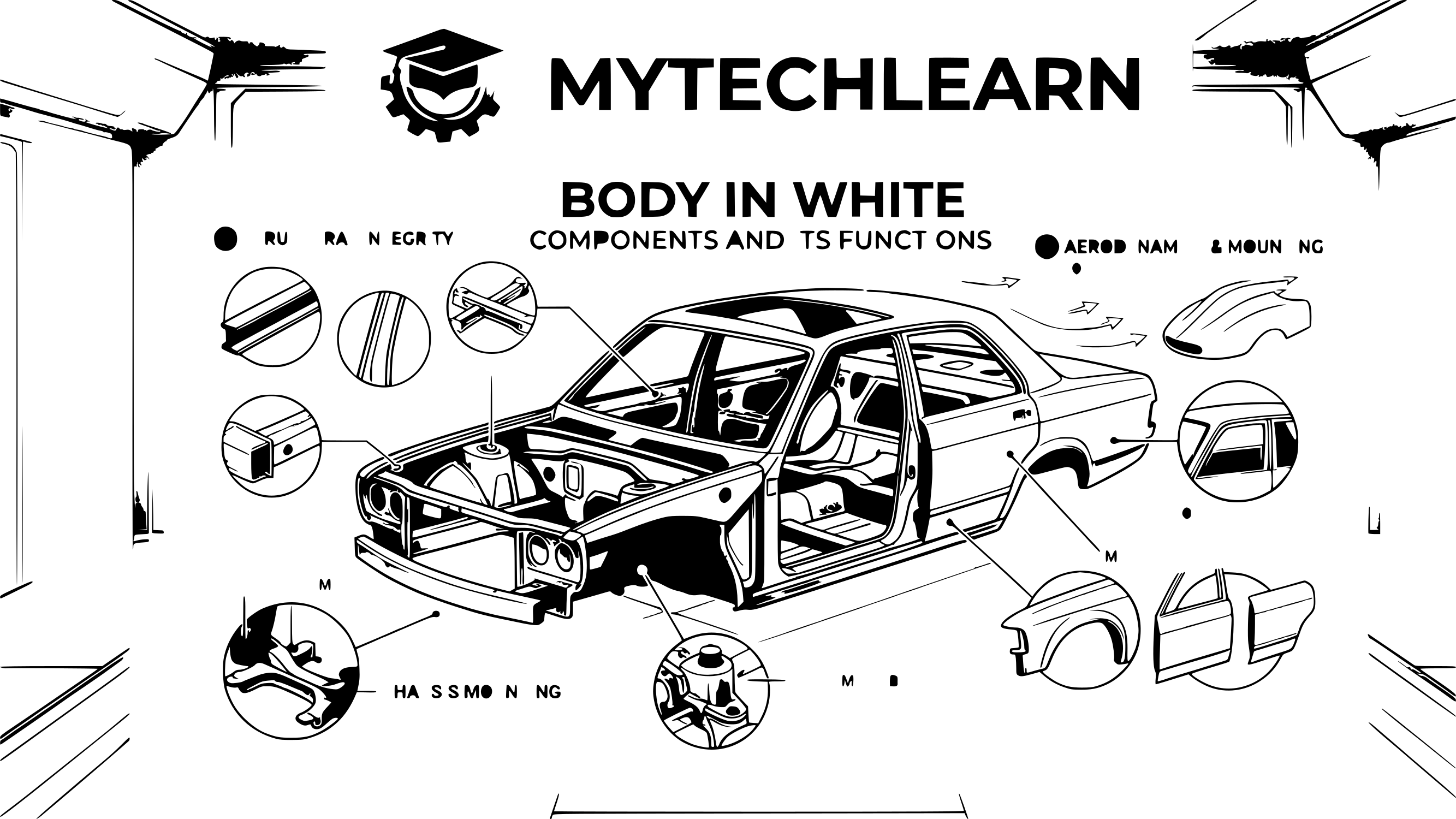
Automotive BIW Design Training — Body-in-White Structural Engineering
Study BIW structural engineering: body architecture, crash load paths, sheet-metal DFM, joining strategy, GD&T stack-up, DFMEA and ECR/ECN control. Build production-ready structural competence for OEM and Tier-1 body-structure roles — with emphasis on engineering decisions and production readiness.
Enquire About BIW TrainingRequest Domain Curriculum
01 · WHAT BIW DECIDES
What BIW Engineering Actually Decides
Key Engineering Decision
BIW decides crash energy paths, body stiffness, dimensional stability of mounting points, and whether the structure can be built at line rate with available joining equipment. A design that is strong on paper but unbuildable or dimensionally unstable fails as an engineering outcome.
Body-in-White is the fixed structural body of a vehicle after its major panels have been joined — before paint, before closures, glass, powertrain and trim are installed. It is the load-bearing skeleton that everything else attaches to, and it sets the limits within which every other system must work.
The engineering importance is easy to state and hard to execute. BIW decides where crash energy goes, how the body resists bending and torsion, which mounting points stay dimensionally stable in production, and whether the vehicle can be built at line rate with the joining equipment available. A body structure that is strong on paper but unbuildable, or buildable but dimensionally unstable, fails as an engineering outcome regardless of how it looks in a model.
This programme treats BIW as a chain of connected decisions rather than a catalogue of panels. Learners work through architecture, load paths, sheet-metal formability, material grade and thickness, joint selection and access, datum strategy, and change control — and are assessed on whether those decisions hold together.
02 · BODY ARCHITECTURE
Body Architecture and Structural Zones
What OEMs & Tier-1 Expect
Engineers must explain how each zone contributes to global body performance, how load paths are continuous, and how interfaces with powertrain, suspension, closures and battery systems are controlled dimensionally and structurally.
Each zone carries a defined structural responsibility and interfaces with systems outside BIW. Learners study zones in terms of what each must do, not merely what it contains.
Front-End Structure
Manages frontal impact energy and carries powertrain and front-suspension interfaces. Front longitudinal rails, crash boxes and bumper reinforcement interfaces, upper rails and shotguns, apron panels, wheelhouses, strut-tower reinforcements, and the dash and toe-board region form the load collection and distribution path.
The engineering question is whether the rail can deform progressively without the dash region intruding into the occupant cell.
Underbody
Connects front, centre and rear structures and carries seat, subframe and — in electric vehicles — battery loads. Front, centre and rear floor panels, the transmission tunnel, floor cross-members, rocker panels and reinforcements, seat and subframe mounting reinforcements all contribute.
Floor continuity and cross-member placement determine how well the body resists bending and how side loads reach the opposite rocker.
Side Body
Provides passenger-compartment integrity and side-impact resistance. A-, B- and C-pillar assemblies and their reinforcements, rocker inner and outer structures, body-side inner panels, roof-side rail connections and door-aperture reinforcements form a ring that must remain continuous through the beltline and rocker junctions.
Upper Body
Supports roof strength and structural continuity. The roof panel, roof rails, roof bows and cross-members, front and rear headers and pillar-to-roof connections determine roof-crush resistance and body torsional behaviour.
Rear-End Structure
Manages rear impact and carries rear-suspension and luggage-compartment requirements. Rear longitudinal rails, rear floor, rear cross-members, rear wheelhouses, rear side members and suspension mounting reinforcements complete the load path.
Boundary note. Doors, hoods, tailgates and decklids are closure systems covered under Closures Engineering. They integrate tightly with BIW through hinges, latches, apertures and seals, but they are not interchangeable with the fixed body structure. Learners who confuse the two struggle in interviews, because the engineering responsibilities and failure modes differ.
03 · LOAD-PATH REASONING
Load-Path Reasoning
Load-path work is the core intellectual discipline of BIW. It is also the area where candidates are most often exposed in technical discussions.
| Structural requirements and what the engineer must establish | Structural requirements and what the engineer must establish |
|---|---|
| Structural Requirement | What the Engineer Must Establish |
| Frontal and rear impact | A continuous, progressive crush path from the rails into the occupant cell, with a defined boundary between energy-absorbing regions and the safety cell |
| Side impact | A load ring through the rocker, B-pillar and roof rail that resists intrusion without breaking continuity at the beltline junction |
| Roof strength | Pillar and roof-rail continuity capable of carrying crush loads to the lower body |
| Bending and torsional stiffness | Cross-member and ring placement that closes load loops rather than leaving open sections |
| Durability and fatigue | Identification of highly loaded mounting areas, stress concentration at holes, flanges and joints, and reinforcement where fatigue risk concentrates |
| NVH behaviour | Structural continuity and joint stiffness as inputs to panel vibration and local resonance behaviour |
The recurring engineering failure is discontinuity — a reinforcement that stops short of the neighbouring panel, a flange that cannot be welded because the gun cannot reach, or a section change that creates a stress riser. Learners are trained to trace a load path from origin to reaction and to identify where continuity is broken and what the consequence is.
Trade-offs that must be argued, not assumed: strength against mass; stiffness against material cost; crash performance against packaging space; structural continuity against manufacturing and tooling access; local reinforcement against part-count reduction.
04 · SHEET-METAL ENGINEERING
Sheet-Metal Engineering and Formability
BIW components are predominantly formed sheet metal, and their geometry must satisfy structural, manufacturing, joining and dimensional requirements simultaneously.
Operations encountered: blanking, piercing, drawing, trimming, flanging, and restriking or restraining operations depending on the tooling route.
Design considerations that drive feasibility: sheet thickness and grade; bend radius relative to material ductility; draw depth against formability; flange width against joining requirements; hole position and edge distance; beads, ribs and local reinforcement features; springback sensitivity; and part release direction.
The four defects learners must be able to predict and prevent
| Sheet-metal defects, causes and design responses | Sheet-metal defects, causes and design responses | Sheet-metal defects, causes and design responses |
|---|---|---|
| Defect | Cause | Design Response |
| Splitting | Excessive stretching or unsuitable forming conditions | Adjust radii, draw depth, material grade or add forming relief |
| Wrinkling | Compressive deformation during forming | Control blank shape, add beads or restrainer features, adjust draw conditions |
| Springback | Elastic recovery after load removal | Section and radius compensation, overbending, or process adjustment |
| Thinning | Local thickness reduction during forming | Reallocate draw, adjust radii, or review material grade for strength retention |
There is no universal bend radius, flange width or draw depth that suits every component. Requirements depend on grade, thickness, forming operation, tooling and supplier capability, and each component must be assessed on its own terms. Learners are taught to state a recommendation with its governing condition, not as a fixed rule.
05 · MATERIAL & THICKNESS
Material and Thickness Selection
Material choice in BIW is a structural argument constrained by formability, joining and cost. Explore our Materials Engineering subject for deeper coverage.
Mild steel. High ductility and formability, low cost. Suited to brackets and panels where forming severity, not strength, governs.
HSLA (high-strength low-alloy). Higher strength with moderate forming capability. Used where structural demand rises but forming severity remains manageable.
AHSS (advanced high-strength steel). Higher strength and crash-performance capability, with increased springback sensitivity and reduced formability window. Grade selection must be matched to the forming route, not to the strength target alone.
Press-hardened steel. Formed hot and quenched in tooling to achieve very high strength. Requires hot-forming process capability and consideration of post-form trimming and joining access.
Aluminium alloys. Used in lightweight body structures and mixed-material architectures. Brings joining compatibility, corrosion and process considerations that must be designed in from the start.
Selection checks applied in the programme: strength and ductility against the forming route; thickness and section geometry against stiffness demand; springback sensitivity against dimensional tolerance; crash and durability requirements against grade; joining compatibility with neighbouring materials; corrosion protection; weight and cost targets; supplier process capability.
Thickness is treated as an outcome of the structural and manufacturing argument — not a starting assumption.
06 · STAMPING DFM METHOD
Stamping DFM Review Method
Design for Manufacturing in BIW means establishing, before tooling is committed, that the part can be formed repeatedly and inspected. The programme teaches a repeatable review sequence:
Establish component function and the structural load it must carry.
Confirm material grade and thickness against that function.
Review the proposed geometry and define the forming direction.
Identify high-risk draw regions — deep pockets, tight radii, rapid section changes.
Check flange geometry against joining requirements and trimming access.
Verify hole, slot and edge-distance requirements.
Assess springback and dimensional risk.
Confirm tooling access, part release and inspection feasibility.
Record the issues and recommend a design or process change with justification.
The output is a written DFM assessment — a technical position with identified risks and recommendations, not a checklist of ticked boxes.
07 · JOINING & ASSEMBLY
Joining Technology and Assembly Sequence
Joining selection is governed by material compatibility, joint loading, access, equipment and quality requirements. Learners compare methods on engineering grounds. See Joining Technology for expanded coverage.
| Joining methods, application logic and design prerequisites | Joining methods, application logic and design prerequisites | Joining methods, application logic and design prerequisites |
|---|---|---|
| Method | Application Logic | Design Prerequisite |
| Resistance spot welding | Primary joining for overlapping steel sheet | Flange width sufficient for the electrode, weld pitch, and gun access from both sides |
| Laser welding | Concentrated heat source for suitable joint configurations | Tight joint fit-up and process access |
| Structural adhesive | Added joint stiffness, sealing and load distribution | Surface preparation, bond-line control and curing route |
| Self-piercing riveting | Mixed-material and selected multi-material joints | Material stack compatibility and tool access |
| Clinching | Mechanical interlock without a fastener | Suitable thickness combination and joint configuration |
| MIG/MAG welding | Structural and bracket applications | Joint design permitting the process |
| Hemming | Closure outer-to-inner panel joining | Flange geometry and hemming process allowance |
Assembly engineering (DFA) checks: joint type against load direction; material compatibility; flange dimensions; joining-tool clearance and access; weld or fastener location and sequence; fixture access; corrosion protection at the joint; inspection feasibility; and repairability. Explore our DFA subject for the fuller method.
The practical constraint that catches most learners is gun access. A weld schedule that cannot be reached by the electrode in a real fixture is not a schedule — it is a drawing note. The programme requires learners to demonstrate that each specified joint is physically achievable in the assembly sequence.
08 · DIMENSIONAL MANAGEMENT
Dimensional Management, GD&T and Fitment
BIW dimensional control decides whether closures, glass, exterior panels and underbody systems can be assembled with consistent gap, flush and functional clearances. Engineers must define locating strategy, datum references and tolerance allocation that protect fitment at production volume.
Explain how load paths remain continuous, how mounting points stay dimensionally stable, how joining sequence affects distortion, and what evidence supports dimensional capability before tooling release.
A panel can meet its own drawing and still cause an assembly problem once neighbouring variation is added. Dimensional control therefore operates at both part and assembly level.
Datum strategy. Identify functional locating features, establish a datum reference structure, apply the 3-2-1 locating principle, and align drawing datums with the assembly locating scheme and inspection routine. A datum scheme that cannot be reproduced by the checking fixture is a datum scheme that will generate disputes at the trial stage.
GD&T application. Form, orientation, location and profile controls; feature control frames; control selection driven by function rather than habit; and clear inspection intent. See our GD&T training subject for the full treatment.
Tolerance stack-up. Identify the dimensional chain, allocate tolerances, compute worst-case and RSS variation across a multi-panel welded assembly, and relate the result to the actual requirement — gap, flush, clearance or aperture dimension. See Tolerance Stack-Up.
BIW fitment interfaces where stack-up matters most: door-aperture dimensional control; hinge and latch mounting accuracy (see Closures Engineering); roof-to-side-body interfaces; windshield and backlight mounting; floor and underbody assembly alignment; and closure gap and flush targets.
Dimensional quality in production. Fixture and locating strategy, hole and slot position control, critical characteristic identification, measurement correlation, and structured root-cause investigation when the body does not meet target.
09 · MANUFACTURING & ASSEMBLY
Manufacturing and Assembly Engineering
A body structure must survive the plant, not only the analysis. See Manufacturing Processes for the wider subject.
Manufacturing considerations: component manufacturing sequence; stamping and tooling feasibility; part locating and positioning; welding and joining sequence; fixture and checking-gauge concepts; robotic access; assembly repeatability; process capability; dimensional inspection; and rework prevention.
The questions a BIW engineer must be able to answer for any proposed structure: can the components be positioned correctly; can the joining tools reach the required locations; is the sequence practical; can the assembly be inspected; are the critical dimensions controlled; and can the process achieve repeatable quality at production rate.
These are the questions that convert a design review from a drawing walkthrough into an engineering discussion. See Documentation & Design Reviews for how this is developed.
10 · RISK, VERIFICATION & CHANGE
Risk, Verification and Engineering Change
DFMEA. Identify component and assembly failure modes, assess effects and causes, rate severity, occurrence and detection, define risk-reduction actions, and maintain traceability from failure mode to design action.
DVP&R. Convert requirements into verification activities, select appropriate tests, analyses and inspection methods, define acceptance criteria, track status and results, and close failures with corrective-action evidence.
BIW verification subjects: dimensional inspection, material verification, joint-quality evaluation, structural and stiffness requirements, durability considerations, corrosion protection, manufacturing feasibility, and assembly and fitment checks.
Scope note. Detailed crash simulation and physical certification require specialist CAE and test capability. This programme develops understanding of the structural design implications and of how engineering teams act on validation feedback — it does not claim to deliver CAE or certification capability.
ECR/ECN. An ECR records the issue or improvement, the technical reason for change, the affected components and interfaces, and the safety, quality, cost and manufacturing impact, and obtains the required approval. An ECN communicates the approved change for controlled implementation — affected parts, drawings and documents, revision and effectivity details, communication to affected functions, and traceability of released information.
Terminology and approval routes vary between organisations. Learners are taught the control principles rather than a single fixed form, because the underlying discipline — propose, assess, approve, implement, trace — is consistent even where the paperwork is not.
11 · PROJECT WORK
Project Work and Expected Evidence
Projects are engineering exercises with a written position at the end. They are representative learning studies, not confidential OEM programmes.
| Project studies and expected evidence | Project studies and expected evidence | Project studies and expected evidence |
|---|---|---|
| Project | What It Covers | Expected Evidence |
| Side-body structural development | Identify A-, B- and C-pillar functions, study rocker and roof-rail connections, trace side-impact load paths, justify material and reinforcement strategy, evaluate section continuity, and identify joining and packaging constraints. | Side-body component map, load-path explanation, material and reinforcement justification, interface and joining review, feasibility observations. |
| Door inner and outer panel engineering | Study inner and outer panel functions, hinge, latch and intrusion-beam interfaces, glass and regulator requirements, hemming principles, joining and assembly requirements, and dimensional and fitment considerations. | Component-function breakdown, interface and packaging study, hemming and joining assessment, dimensional control considerations. |
| Underbody reinforcement development | Identify the component's structural role, study floor, cross-member and rocker interfaces, understand load transfer and mounting requirements, justify material and thickness, assess stamping feasibility, and evaluate joining access and sequence. | Component analysis, structural interface assessment, material and manufacturing justification, joining feasibility review, improvement recommendations. |
| BIW joint and weld strategy | Identify joint locations, compare joining technologies, review weld access and flange geometry, study sequence and fixture requirements, check material compatibility, and identify inspection requirements. | Joint selection justification, joining-location plan, weld-access assessment, assembly sequence review, risk observations. |
| Component feasibility assessment | Review function and requirements, material and thickness, forming feasibility, springback and dimensional risk, joining and inspection access, and potential failure modes, and recommend practical improvements. | Feasibility report, DFM assessment, joining and assembly review, dimensional risk observations, DFMEA input. |
Assessment weighs technical correctness, reasoning quality, documentation discipline and defensibility under questioning. A recommendation that cannot survive review questioning is treated as incomplete work.
12 · COURSE OUTCOMES
Course Outcomes
What a learner can demonstrate at the end of the BIW domain, across architecture, feasibility, joining, dimension and change.
| Outcome areas and learner capability | Outcome areas and learner capability |
|---|---|
| Outcome Area | Learner Can Demonstrate |
| Body architecture | Explain BIW structural zones, the responsibility of each, and how zones interface with non-BIW systems |
| Load-path reasoning | Trace front, rear, side and roof load paths, identify discontinuities, and justify reinforcement or section changes |
| Sheet-metal feasibility | Predict splitting, wrinkling, springback and thinning risk, and recommend geometry or process changes |
| Material and thickness | Select grade and thickness against structural, forming, joining and cost requirements, with the reasoning stated |
| DFM assessment | Conduct a structured stamping feasibility review and produce a defensible written assessment |
| Joining and assembly | Compare joining methods on engineering grounds, verify access and flange geometry, and sequence an assembly |
| Dimensional management | Establish a functional datum scheme, apply GD&T, and compute worst-case and RSS stack-ups for a welded assembly |
| Risk and validation | Structure a DFMEA, link failure modes to design actions, and define DVP&R activities |
| Change control | Raise a change with impact assessment and control an approved revision with traceability (ECR/ECN) |
| Technical communication | Present and defend body-structure decisions in a review setting |
These outcomes represent learning capability. Independent performance in a live programme also depends on workplace exposure, programme-specific requirements and employer expectations.
13 · CAREER OUTCOMES
Job Opportunities
Roles this BIW domain supports, and what the work typically involves.
| BIW roles and typical work | BIW roles and typical work |
|---|---|
| Role | What the Work Involves |
| BIW Design Engineer | Body structure components, interfaces, material selection, feasibility and documentation |
| Body Structure Engineer | Structural architecture, load paths, stiffness, reinforcement strategy and body-level performance |
| Sheet Metal Design Engineer | Sheet-metal component engineering, forming feasibility, material selection and stamping-related design decisions |
| BIW Manufacturing / DFM Engineer | Stamping feasibility, tooling reviews, joining access, assembly requirements and manufacturing problem-solving |
| BIW Dimensional Engineer | Datum strategy, GD&T, stack-up, variation analysis, fixture concepts and body assembly quality |
| Closures Design Engineer | Doors, hood and tailgate structures, hemming, joining, fitment and dimensional requirements |
| Product Design Release Engineer | Documentation, design reviews, BOM control, change management and release activity (ECR/ECN) |
Employer types: passenger and commercial vehicle OEMs, two-wheeler manufacturers, Tier-1 body and structure suppliers, engineering R&D service providers, and EV manufacturers developing new body architectures.
Job titles and responsibilities vary by company. Some positions also require specialist analysis capability, PLM experience or prior programme exposure; candidates should verify requirements in the specific job description.
15 · WHO SHOULD TAKE THIS DOMAIN
Who Should Take This Domain
This BIW domain suits learners building a structural specialisation or moving into design from adjacent functions.
Mechanical and automobile engineering students building a structural specialisation before final-year placements — start with Automotive Fundamentals.
Production and manufacturing graduates who want to move from process execution toward design-side feasibility.
Diploma and technical-training holders strengthening component and drawing knowledge for body-structure roles.
Working engineers in quality, production or drafting who intend to move into structural design.
Career-restart engineers refreshing fundamentals and current development methods.
Assumed foundation: engineering mechanics, strength of materials, material properties, basic manufacturing processes, engineering drawing interpretation and basic engineering mathematics. Prior BIW experience is not required.
16 · FREQUENTLY ASKED QUESTIONS
Frequently Asked Questions
1. BIW or closures — how do I know which domain fits me better?
2. How much mathematics and structural mechanics is actually used in BIW work?
3. I have no BIW experience and low academic marks. Is a structural role realistic?
4. What does springback mean in practice, and why does it matter at design stage?
5. Why is weld flange width a design decision rather than a manufacturing detail?
6. How much of BIW work is crash simulation, and will this programme teach CAE?
7. Should I learn advanced high-strength steel grades before applying for BIW roles?
8. Which BIW projects should go into a fresher portfolio?
CONTINUE LEARNING
Explore Related Domains & Methods
The BIW domain shares interfaces with every other engineering system and applies every product-development method. Continue into the related pages below.
Closures EngineeringInterior Product EngineeringExterior Product EngineeringSeating EngineeringEV EngineeringLighting EngineeringMaterials EngineeringManufacturing ProcessesJoining TechnologyPackaging & InterfacesGD&T TrainingTolerance Stack-UpDFMDFADFMEADVP&RAPQP & PPAPECR & ECNQuality EngineeringDocumentation & ReviewsCase StudiesPractical Assignments
COMPONENT ENGINEERING DEEP DIVE
BIW front longitudinal rail: function, load path and manufacturing feasibility
Educational schematic for engineering discussion. Not an OEM-released drawing or vehicle-specific design.
Component: Front longitudinal rail. A primary front-structure member that participates in managing crash loads and transferring forces into the surrounding body structure. Its exact role depends on the vehicle architecture and crash strategy.
| Engineering lens | What the engineer must evaluate |
|---|---|
| Function and structure | Evaluate controlled deformation, load transfer to adjoining structures, local buckling, section stability, joint strength and interaction with the crash box, front cross member, apron, floor and subframe interfaces. |
| Material selection | Steel grade and gauge are selected from programme targets, forming capability, joining, corrosion protection, mass and validation. A higher-strength grade is not automatically better if forming, joining or crash behaviour is compromised. |
| Manufacturing, joining and assembly | Stamping/forming feasibility includes draw direction, section depth, flange continuity, radii, beads, thinning, springback, trimming and tool access. Joining review includes weld access, stack-up, flange geometry, adhesive compatibility and corrosion protection. |
| Packaging and dimensional control | Use functional datums and geometric controls that relate the rail to body build and mating structures. Validate dimensional strategy with fixture/inspection access and the actual build sequence. |
| Quality, risk and validation | DFMEA should consider inadequate energy management, local instability, joint separation, corrosion and dimensional mismatch. Verification evidence is defined by programme crash, durability, dimensional and manufacturing requirements; never substitute generic limits for OEM targets. |
Expected engineering output
Prepare a component function statement, interface register, material/process rationale, DFM/DFA review, critical-feature and datum rationale, risk assessment, verification outline and change-impact checklist. State all assumptions and trace every acceptance criterion to an authorised requirement.
Build your automotive engineering knowledge
Explore the technical subjects or contact MYTECHLEARN about your learning objectives.
Enquire Now
PRACTICAL OUTPUT
Sample BIW Engineering Deliverables
Learners develop assessed work that demonstrates engineering reasoning, not only tool operation.